The purpose of Missile graphics is to represent very small shapes; Players represent medium-sized shapes. For instance, in the game Outlaw/Howitzer from APX Software (see Photos 1 & 2), the stationary background displays (battlefields) are pixel (PLOT) graphics, while the animated player components are PMGs. The gunfighters in Outlaw are two Players of different colors overlapping one another. The PMG priority level is set so that the overlapping area of the Players produces a third color. Watch future installments for discussions of priorities and collision registers. In Howitzer, the tanks also comprise multiple Player graphics to show extra detail. The concept of each game is for two real-world players (one can be the computer) to eliminate one another by firing a weapon. The bullets from the guns in Outlaw and the artillery shells from the tanks in Howitzer are Missile graphics. Players can represent any major moving object in a video game, and Missiles can represent whatever they expel.
PMGs have other applications. Since PMGs stretch from the top of the screen to the bottom, they can join normal pixel graphics to add colors to stationary displays. For example, if you have drawn a planetary terrain, and you need to draw a spaceship sitting in the background, a PMG can add an extra touch of color. Groups of Players and Missiles can also be combined to form colorful accents for any display.
Missiles, like Players, come in all shapes and sizes. Almost all the options for Players are available for Missiles. In most cases, even the same registers control Players and Missiles. Most of the procedures to enable Missiles are the same for Players. If you are using Player graphics, you have already done most of the important work, such as setting PMBASE to point at PMG RAM.
Tables 1a and 1b list all the registers this article discusses. SDMCTL is the first register of interest to us in the Tables. Figure 1 is a reprint of the bit map for SDMCTL, which appeared in Issue 42. Bit 4 selects the Player 1 Missile resolution. The two modes of vertical resolution that Players allow - single scan line and double - also apply to Missiles. The resolution mode selected controls both Players and Missiles. SDMCTL also contains the bits that enable GTIA to access PMG RAM (GTIA PMG DMA) directly. GTIA can access PMG RAM if bit 2's value is 1. Bit 0 of the GRACTL register, shown in Figure 2, controls the Missile graphics registers. When bit 0 is set to 1, the Missile graphics registers are enabled. To fully enable PMGs, you must set the proper bits in both SDMCTL and GRACTL.
Table 1a
IMPORTANT PMG SHADOW REGISTER LOCATIONS
| Hex | Dec | Title | Register Description |
|---|---|---|---|
| 006A | 00106 | RAMTOP | Top of RAM pointer. |
| 022F | 00559 | SDMCTL | Direct Memory Access Control. |
| 02C0 | 00704 | PCOLR0 | Player 0 color. |
| 02C1 | 00705 | PCOLR1 | Player 1 color. |
| 02C2 | 00706 | PCOLR2 | Player 2 color. |
| 02C3 | 00707 | PCOLR3 | Player 3 color. |
Table 1b
IMPORTANT PMG HARDWARE REGISTER LOCATIONS
| Hex | Dec | Title | Register Description |
|---|---|---|---|
| D000 | 53248 | HPOSP0 | Player 0 horizontal position. |
| D001 | 53249 | HPOSP1 | Player 1 horizontal position. |
| D002 | 53250 | HPOSP2 | Player 2 horizontal position. |
| D003 | 53251 | HPOSP3 | Player 3 horizontal position. |
| D004 | 53252 | HPOSM0 | Missile 0 horizontal position. |
| D005 | 53253 | HPOSM1 | Missile 1 horizontal position. |
| D006 | 53254 | HPOSM2 | Missile 2 horizontal position. |
| D007 | 53255 | HPOSM3 | Missile 3 horizontal position. |
| D01D | 53277 | GRACTL | Player/Missile Graphics control. |
| D407 | 54279 | PMBASE | Memory page of PMG data. |
Figure 1.

SDMCTL - DIRECT MEMORY ACCESS CONTROL ($022F)
A shadow register for DMACTL ($D400) which writes data into the DMA control
register in hardware.

Bit Map:
       ┌───┬───┬───┬───┬───┬───┬───┬───┐
Bit:   │ 7 │ 6 │ 5 │ 4 │ 3 │ 2 │ 1 │ 0 │
       └───┴───┴───┴───┴───┴───┴───┴───┘

     B7, B6 - Not used
         B5 - 1 Enables antic DMA instruction fetch.
         B4 - 1 Enables single line PMG resolution.
              0 Enables double line PMG resolution.
         B3 - 1 Enables player DMA.
         B2 - 1 Enables missile DMA.
     B1, B0 - 0, 0 No playfield DMA.
              0, 1 Enables narrow playfield DMA. (128 color clocks wide)
              1, 0 Enables narrow playfield DMA. (160 color clocks wide)
              1, 1 Enables wide playfield DMA. (192 color clocks wide)
Figure 2.

GRACTL - GRAPHICS CONTROL ($D01D)
Writes data to the graphic control register in hardware.

Bit Map:
       ┌───┬───┬───┬───┬───┬───┬───┬───┐
Bit:   │ 7 │ 6 │ 5 │ 4 │ 3 │ 2 │ 1 │ 0 │
       └───┴───┴───┴───┴───┴───┴───┴───┘

     B7, B6
 B5, B4, B3 - Not used
         B2 - 1 Enables input latches for TRIG0-TRIG3 registers.
              0 Resets latches and TRIG0-TRIG3 act as normal.
         B1 - 1 Enables player DMA for player graphic registers.
         B0 - 1 Enables missile DMA for missile graphic registers.
If only SDMCTL is set up, the DMA (direct memory access) occurs, but the PMG processing hardware is still "turned off." The result is that the computer processes PMGs, but they look wrong when displayed. The DMA freezes the microprocessor while another circuit uses the address and data lines to look at data in memory. This slows down the microprocessor, and the computer's overall speed decreases. When all the circuits that use DMA or interrupts are working, the Atari runs approximately 40 percent more slowly than normal, but some of these circuits are necessary for normal operation. Always disable features such as PMGs, when they are not needed.
Missiles are less versatile than Players with respect to color. Each Missile's color is the same as its corresponding Player, because Missile's original purpose is to represent objects that Players expel. The next installment of Frontier will discuss methods to make all the Missiles a different color from that of any Player and to combine all four Missiles to form a fifth Player.
Figures 3a and 3b represent the memory map for PMG RAM in double and single line resolution modes. Missiles, like Players, are located at an offset from PMBASE. PMBASE is one of the locations that you must set up when enabling Players. To find Missile RAM, add the offsets listed in the figures to the actual address of PMG RAM. If PMBASE is set to page 125 ($7D), then PMG RAM starts at 32000 ($7D00), and the start of Missile RAM is at 32384 ($7E80) for double line or 32768 ($8000) for single line resoluton.
Figure 3a.

      Double Line

┌───────────────────┐ PMBASE
│                   │
│                   │
│      Unused       │
│                   │
├────┬────┬────┬────┤  +384
│ M3 │ M2 │ M1 │ M0 │
├────┴────┴────┴────┤  +512
│     Player 0      │
├───────────────────┤  +640
│     Player 1      │
├───────────────────┤  +768
│     Player 2      │
├───────────────────┤  +896
│     Player 3      │
└───────────────────┘ +1024

Figure 3b.

      Single Line

┌───────────────────┐ PMBASE
│                   │
│                   │
│                   │
│                   │
│                   │
│      Unused       │
│                   │
│                   │
├────┬────┬────┬────┤  +768
│ M3 │ M2 │ M1 │ M0 │
│    │    │    │    │
├────┴────┴────┴────┤ +1024
│     Player 0      │
│                   │
├───────────────────┤ +1280
│     Player 1      │
│                   │
├───────────────────┤ +1536
│     Player 2      │
│                   │
├───────────────────┤ +1792
│     Player 3      │
│                   │
└───────────────────┘ +2048
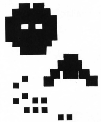
Although Missile graphics function essentially the same as Players, using them presents programmers with a new concept to understand and a new problem in program development. Missiles are mapped in memory in a very complicated way. I have mentioned in the past that Players require one byte for each horizontal line of the shape. Each byte consists of eight bits that correspond to the eight pixels in each line of the Player. Missiles differ in this respect by using only one-fourth of a byte for each line, which gives a horizontal resolution of two bits or pixels. This means that one line for all four Missiles can be stored in one byte. UnfortunateIy, this is exactly what is done.
Figure 4 shows graphically how GTIA interprets Missile RAM. Each byte of Missile RAM comprises four groups of two bits. The first two bits (0 and 1) represent Missile 0, the next two bits (2 and 3) are Missile 1, and so on. Each group of bits in a Missile shape byte is separate and distinct to GTIA, but BASIC treats the memory location into which they are mapped as one location with one combined value. This allows Missiles to use a small amount of RAM, but complicates attempts to modify Missiles independently.
Figure 4

               MISSILE RAM BIT MAP

                  MISSILE  DATA
             M3     M2     M1     M0
          ┌──────┬──────┬──────┬──────┐
 1 BYTE { │  00  │  10  │  10  │  11  │
          ├──────┼──────┼──────┼──────┤
          │  00  │  11  │  11  │  00  │
          ├──────┼──────┼──────┼──────┤
          │  00  │  11  │  10  │  11  │
          ├──────┼──────┼──────┼──────┤
          │  00  │  11  │  01  │  00  │
          ├──────┼──────┼──────┼──────┤
          │  00  │  10  │  01  │  11  │
          ├──────┼──────┼──────┼──────┤
          │  00  │  01  │  00  │  00  │
          ├──────┼──────┼──────┼──────┤
          │  00  │  01  │  11  │  11  │
          ├──────┼──────┼──────┼──────┤
          │  00  │  01  │  01  │  00  │
          ├──────┼──────┼──────┼──────┤
          │  00  │  01  │  01  │  11  │
          ├──────┼──────┼──────┼──────┤
          │  00  │  11  │  11  │  00  │
          ├──────┼──────┼──────┼──────┤
          │  00  │  11  │  10  │  11  │
          ├──────┼──────┼──────┼──────┤
          │  00  │  11  │  01  │  00  │
          ├──────┼──────┼──────┼──────┤
          │  00  │  11  │  01  │  11  │
          ├──────┼──────┼──────┼──────┤
          │  00  │  10  │  10  │  00  │
          └──────┴──────┴──────┴──────┘
                     8  BITS
          └─────────────┬─────────────┘
                     1  BYTE
Missile motion methods are identical in theory to those for Players. The same algorithms used for moving Players work for Missiles. For horizontal motion, Missiles have a set of hardware registers analogous to the Player horizontal-position registers. Their locations appear in Table 1 b as HPOSM0 through HPOSM3. The value placed here is a color-clock value (see issue #42) that determines the horizontal position of the missile shape.
10000 FOR X=1664 TO 1755
10010 READ Y:POKE X,Y:NEXT X
10020 DATA 104,104,133,213,104,133
10030 DATA 212,104,104,168,104,104
10040 DATA 170,169,3,192,0,240,5,10
10050 DATA 10,136,144,247,141,219,6
10060 DATA 160,255,138,208,31,168
10070 DATA 173,219,6,73,255,49,212
10080 DATA 145,212,200,173,219,6,49
10090 DATA 212,136,17,212,145,211,200
10100 DATA 192,255,208,231,169,0,145
10110 DATA 212,96,173,219,6,73,255,49
10120 DATA 212,145,212,136,173,219,6
10130 DATA 49,212,200,17,212,145,212
10140 DATA 136,208,233,169,0,145,212
10150 DATA 96,96
Vertical Missile motion, however, is more complicated, because of the bitmapping. As with Players, you must rotate the shape data of Missiles in memory to accomplish vertical motion. With Missiles, this process is more difficult, since we are not moving whole bytes of Player data, but a few bits at a time. Using a routine in BASIC to do this would take so long that you could probably enjoy a quick frontal lobotomy before it was finished executing. The only reasonable approach to something this complicated and time-consuming is to use machine language, so Kerry Shetline and I wrote the program in Listing 1a. This two-bit scrolling routine allows fast vertical movement of Missile graphics. The BASIC code pokes in the machine language routine from DATA statements. After running the program, you can move Missiles with the following BASIC USR statement:
var = USR(addr, pm base, missile, direction)
var is a dummy variable for the USR command.
addr is the address of the machine-language routine (1664 decimal).
pmbase is the absolute address of PMG RAM plus the Missile offset.
missile is the number of the Missile you wish to move (0-3).
direction is 0 to move up or 1 to move down.
Listing 1b is the assembly source code for the Missile-move routine. I 'll explain it line by line to help you understand Missile vertical movement. The first instruction after setting the object code assembly address is a PLA instruction . The first byte on the stack is the number of parameters in the USR function call, excluding the address of the user routine (1664), which is not placed on the stack. In this case, there are always three parameters, so the routine does nothing with the first value it pulls from the stack. Lines 130 - 160 put the address of PMBASE into a free zero-page location for use with the 6502 indirect-addressng instructions. Lines 170 - 190 place the number of the Missile to move into the Y register. Lines 200 - 220 place the direction (0 or 1) into the X register temporarily. Line 230 sets up the bit mask for Missile number 0 in the Accumulator (or A register) . What is a bit mask, and what does masking do?
0000         0100        *=   $0680     ;ASSEMBLY LOCATION.
             0110 ;
0680 68      0120 INIT   PLA            ;REMOVE # OF ARCS.
0681 68      0130        PLA            ;GET MSB OF MISSILE
0682 85D5    0140        STA  $D5       ; RAM AND STORE IT.
0684 68      0150        PLA            ;GET LSB OF MISSILE
0685 85D4    0160        STA  $04       ; RAM AND STORE IT.
0687 68      0170        PLA            ;DISCARD MSB AND PUT
0688 68      0180        PLA            ; LSB OF THE MISSILE
0689 A8      0190        TAY            ;  TO MOVE INTO 'Y'.
068A 68      0200        PLA            ;DISCARD MSB AND PUT
068B 68      0210        PLA            ; LSB OF DIRECTTION
068C AA      0220        TAX            ;  TO MOVE INTO 'X'.
068D A903    0230        LDA  #$03      ;SET UP BIT MASK.
068F C000    0240 ADJUST CPY  #$00      ;MASK ADJUSTED?
0691 F005    0250        BEQ  PPM       ;SAVE MASK IF O.K.
0693 0A      0260        ASL  A         ;SHIFT MASK TO POINT
0694 0A      0270        ASL  A         ; TO NEXT MISSILE.
0695 88      0280        DEY
0696 90F7    0290        BCC  ADJUST    ;CHECK IF DONE.
0698 8DDB06  0300 PUTMSK STA  MASK      ;SAVE MISSILE MASK.
069B A0FF    0310        LDY  #$FF      ;SETUP MOVE OFFSET.
069D 8A      0320        TXA            ;RESTORE DIRECTION.
069E D01F    0330        BNE  DOWN      ;MOVE UP IF ZERO.
06A0 A8      0340        TAY            ;FIX OFFSET FOR UP.
             0350
06A1 ADDB06  0360 UP     LDA  MASK      ;GET MISSILE MASK
06A4 49FF    0370        EOR  #$FF      ; AND INVERT IT.
06A6 3104    0380        AND  ($D4),Y   ;REMOVE THE EXISTING
06A8 9104    0390        STA  ($D4),Y   ; MISSILE BITS.
06AA C8      0400        INY            ;POINT TO NEW BITS.
06AB ADDB0674I0          LDA  MASK      ;GET MISSILE MASK
06AE 3104    0420        AND  ($D4),Y   ; AND EXISTING BITS.
06B0 88      0430        DEY            ;POINT TO DESTINATION.
06B1 1104    0440        ORA  ($D4),Y   ;ADD ONLY MISSILE
06B3 9104    0450        STA  ($D4),Y   ; BITS AND SAVE.
06B5 C8      0460        INY            ;POINT BACK AGAIN.
06B6 C0FF    0470        CPY  #$FF      ;CHECK IF LAST
06B8 D0E7    0480        BNE  UP        ; MISSILE BITE.
06BA A900    0490        LDA  #$00      ;ZERO OUT OLD
06BC 8104    0500        STA  ($D4),Y   ; EDGE CONTENTS.
06BE 60      0510        RTS            ;ALL DONE.
             0520
06BF AD0806  0530 DOWN   LDA  MASK      ;GET MISSILE MASK
06C2 49FF    0540        EOR  #$FF      ; AND INVERT IT.
06C4 3104    0550        AND  ($D4),Y   ;REMOVE EXISTING
06C6 9104    0560        STA  ($D4),Y   ; MISSILE BITS.
06C8 88      0570        DEY            ;POINT TO NEW BITS.
06C9 ADDB06  0580        LDA  MASK      ;GET MISSILE MASK
06CC 3104    0590        AND  ($D4),Y   ; AND EXISTING BITS.
06CE C8      0600        INY            ;POINT TO DESTINATION.
06CF 1104    0610        ORA  ($D4).Y   ;ADD ONLY MISSILE
06D1 9104    0620        STA  ($D4),Y   ; BITS AND SAVE.
06D3 88      0630        DEY            ;CHECK FOR LAST
06D4 D0E9    0640        BNE  DOWN      ; MISSILE BYTE.
06D6 A900    0650        LDA  #$00      ;ZERO OUT OLD
06D8 9104    0660        STA  ($D4),Y   ; EDGE CONTENTS.
06DA 60      0670        RTS            ;ALL DONE.
             0680 ;
06DB 60      0690 MASK   RTS            ;TEMPORARY STORAGE.
Whenever you modify a Missile shape, you should modify only the bits in RAM associated with that Missile. For example, if a line of a Missile 2 shape requires the left pixel to be turned on, then bit 4 must be set to 0 and bit 5 must be set to 1. A byte with these bits would have a decimal value of 32. To turn on the left pixel in the fortieth line of Missile 2, we would have to store (or POKE from BASIC) a value of 32 into the fortieth byte of Missile RAM. Not so difficult, right? Wrong. What if the fortieth byte of Missile RAM also contained important bits of data for Missile 3? When we put the value of 32 into byte 40, the bits for Missile 3 would be erased, because 32 is the value for bits 4 and 5 only. If there are other bits of Missile data in the fortieth byte, those bits must remain unchanged . Instead of putting a 32 into byte 40, we must add 32 to what is already in byte 40. But that assumes bits of 4 and 5 were zero to start with. If byte 40 already contains the shape data for Missile 2, then adding 32 does not yield the correct result. Before adding the new bit values into byte 40, we must set the old bits to zero.
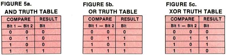
Masking is a machine language technique for operating on specific bits of a byte, using logical (bit-wise) operators such as AND, OR, and XOR (Exclusive OR). The corresponding 6502 instructions are AND, ORA, and EOR. BASIC has no quick or simple way to do this. Even though BASIC contains AND and OR operators, they don't work like logical AND and OR. BASIC does not work on numbers bit-by-bit, the way logical operators and 6502 machine code do. Truth tables describe how a logic circuit reacts to two input signals. When combining two bytes using logical operators to compute a new value, it examines each byte, bit by bit. Each of the logical operators reacts differently to comparisons of the same values. Figures 5a, 5b, and 5c contain the truth tables for the AND, OR, and XOR operators. The logical operator AND results in a 1 bit only when the first bit and the second bit are 1; all else results in a 0 bit. OR results in a 1 bit when the first bit or the second bit or both are 1; a zero results only when both are 0. XOR results in a 1 bit when both bits are different (one of the bits is 1 and the other bit is 0) , but not when they are both the same. For example, 102 ($66 or 01100110 binary) AND 85 ($55 or 01010101 binary) is 68 ($44 or 01000100 binary); 102 OR 85 is 119 ($77 or 01110111 binary); and 102 XOR 85 is 51 ($33 or 00110011 binary). Note that combining one value and another with XOR inverts each bit in the second value that corresponds to a 1 bit in the first.
These commands are an excellent addition to any programming language, and mandatory for working with Missiles. Listing 2a is an assembly source code listing of the routine used by Listing 2b, which is a short BASIC routine that adds these three logical operator commands to Atari BASIC. The source code deserves some close scrutiny by 6502 programmers. It uses a self-modifying code technique that is not readily apparent. The LDA statements in lines 300 - 340 are not permanent. All of the operands (the numbers following the LDA mnemonic) change every time the routine is called. However, the most unusual technique in this routine is replacing the second and fourth LDA opcodes (mnemonics) with one of four bytes from the table at line 390. Depending on the command number (1 -3) the LDA opcode is replaced with the AND, ORA, or EOR opcode. In case an illegal command number has been entered, line 140 masks off the value of the command number to 0 - 3. The table is arranged so that, if the command number is illegal (equal to zero), then the RTS instruction at the end of the routine (which is the first entry in the table as well) replaces the LDA opcode. This has the effect of skipping the routine entirely. This method yields code that is both compact and complicated.
0000           0100            *=     $600
0600 68        0110            PLA                 :REMOVE # OF ARGS.
0601 68        0120            PLA                 ;DISCARD MSB OF CMND#.
0602 68        0130            PLA                 ;GET LSB OF CMND# AND
0603 2903      0140            AND    #$03         ; MASK OFF BAD BITS.
0605 AA        0150            TAX                 ;SAVE FOP TABLE LOOKUP.
0606 68        0160            PLA                 ;GET MSB OF VALUE1.
0607 8D2006    0170            STA    H1+1         ;SAVE IN 3RD LDA VALUE.
060A 68        0180            PLA                 ;GET LSB OF VALUE1.
060B 8D2606    0190            STA    L1+1         ;SAVE IN 3RD LDA VALUE.
060E 68        0200            PLA                 ;GET MSB OF VALUE2.
060F 8D2206    0210            STA    H2+1         ;SAVE IN 2ND LDA VALUE.
0612 68        0220            PLA                 ;GET LSB OF VALUE2.
0613 8D2806    0230            STA    L2+1         ;SAVE IN 4TH LDA VALUE.
0616 BD2B06    0240            LDA    TABLE,X      ;LOOKUP LOGIC OPCODE
0619 8D2106    0250            STA    H2           ; IN TABLE AND STORE
061C 6D2706    0260            STA    L2           ;  AT  2ND &4TH LDA.
               0270 ;
               0280 : SELF MODIFYING CODE.
               0290 ;
061F A900      0300 H1          LDA     #$00       ;VALUE CHANGEE.
0621 4900      0310 H2          LDA     #$00       ;EVERYTHING CHANGES.
0623 85D5      0320             STA     $D5        ;SAVE MSB FOR USR.
0625 A900      0330 L1          LDA     #$00       ;VALUE CHANGES.
0627 A900      0340 L2          LDA     #$00       ;EVERYTHING CHANGES.
0629 85D4      0350             STA     $D4        ;SAVE LSB FOR USR.
               0360 ;
               0370 ;    TABLE OF MODIFYING OPCODES.
               0380 ;
062B 60        0390 TABLE       .BYTE $60          ;'RTS' FOR INVALID.
062C 29        0400             .BYTE $29          ;'AND' IMMEDIATE.
062D 09        0410             .BYTE $09          ;'OR'  IMMEDIATE.
062E 49        0420             .BYTE $49          ;'EOR' IMMEDIATE.
10000 FOR X:1536 TO 1582
10010 READ Y:POKE X,Y:NEXT X
10020 DATA 104,104,104,41,3,170,104
10030 DATA 141,32,6,104,141,38,6,104
11040 DATA 141,34,6,104,141,40,6,189
10050 DATA 43,6,141,33,6,141,39,6,169
10060 DATA 0,0,0,133,213,169,0,0,0
10070 DATA 133,212,96,41,9,73
Use the new commands in the same manner as the Missile moving routine. After running the program to install the machine-language routine, you can access the routine with the BASIC USR function in the format:
var = USR(addr, cmnd#, valuel, value2)
Where:
var is the variable in which the result is stored.
addr is the address of the machine language user routine.
cmnd# is the number of the command (1 = AND, 2=OR, 3=XOR).
value1 is the first value to be evaluated.
value2 is the second value to be evaluated.
Note that you can also use the USR function in IF and PRINT statements.
For example:
PRINT USR(1536, 1,17,20) displays the value of 17 AND 20.
IF USR(1536,3,A,B) THEN PRINT CHR$(125); clears the screen if A XOR B is not zero.
Referring back to listing 1b, a bit mask is a byte value with a specific pattern of bits to isolate and operate upon corresponding bits in another value. Since Missiles are two bits wide, a mask for anyone Missile would have to be two bits wide. The value of three selected in line 230 is there because three in binary is 00000011. The ones in this value correspond to the position of the bits for Missile 0 in a byte of Missile RAM. Combining this mask and any other byte with the AND operator leaves only the contents of the first two bits intact.
Lines 240 - 290 shift the bit mask in the Accumulator to line up with the number of the Missile we wish to move. The ASL A instruction has the effect of shifting all the bits in the Accumulator one bit to the left. Bit 7 moves to the Carry flag, bits 6 through 0 move to bits 7 through 1, and a 0 is put into bit 0. You can think of the Carry flag as a 1-bit storage location, although its main purpose is quite different. The net result of both ASL A's is to shift the mask over two bits. This has the effect of pointing the mask to the next set of Missile bits. Since the Y register currently contains the number of the Missile we wish to move, we can use it as a counter that tells us when to stop shifting the mask.
Line 240 tests to see if the shifting is complete. If Y currently holds a 0, then the mask has been shifted the correct number of bits. Line 250 jumps past the mask shifting routine if Y equals 0. The ASL A's in lines 260 and 270 move the mask, and lines 280 and 290 decrease Y by one and branch back to continue the shifting routine.
Line 300 stores the finished mask temporarily in a free memory location. Line 310 sets up the memory offset pointer in Y, which will be used with the indirectaddressing instructions later. The Y register can act as an offset to a memory address in page zero. For example, if memory locations $D4 and $D5 contain the value 32768 ($8000) and Y contains 0, the instruction LDA ($D4),Y puts the contents of the memory location 32768 into the Accumulator. However, if Y contains 32 ($20), the same instruction puts the contents of memory location 32800 ($8020) , which is 32768 plus 32 ($8000 + $20), into the Accumulator. In the Missile move routine, the Y register is used as an offset into the Missile RAM. By incrementing and decrementing Y, the routine can step through Missile memory without having to calculate new memory addresses for each byte.
Lines 320 - 330 load the Accumulator with the direction value previously stored in the X register, then branch to the DOWN routine if the direction is non-zero. Line 340 adjusts the offset pointer for the UP routine.
Lines 360 - 510 contain the UP routine, which is functionally identical to the DOWN routine, except for the Y offset pointer. All of the increment and decrement Y instructions (INY, DEY) in the DOWN routine are the opposite of those in the UP routine, and the conditional test at the end of the routine is for a different value. Because the two routines are so similar, I'll discuss the UP routine only.
Lines 360 and 370 retrieve the mask value from the temporary memory storage location and invert it with the XOR (EOR) logical operator. Combining the Accumulator and a value of 255 ($FF or 11111111 binary) with this operator inverts every bit in the Accumulator. In Line 380, the inverted mask, along with the logical operator AND, erase the two bits of the selected Missile in the selected byte. Since the mask in the Accumulator has a 1 in the bits that do not correspond to the Missile being modified, only the chosen Missile's data can change. Line 390 stores the new byte in place of the original contents of the Missile shape byte. Lines 400 - 450 masks the byte to be moved to retain only the selected Missile bits in the Accumulator. Next, the OR function installs the resulting value without altering the other Missile data in the destination byte.
To explain the entire routine, I'll use another example. Locations $D4 and $D5 contain the value 16000 ($3E80); the Y register contains 0; location 16000 ($3E80) contains 44 ($2C or 00101100 binary); location 16001 ($3E81) contains 229 ($E5 or 11100101 binary); and the MASK location is set for Missile 1 (mask = 00001100 binary).
At the beginning of the UP routine, the Accumulator is loaded with the Missile bit mask, which the EOR #$FF statement then inverts (Accumulator = 11110011 binary). Next, we eliminate the old Missile data at location 16000 with an AND instruction, combining the contents (00101100 binary) with the Accumulator (11110011 binary). The result (00100000 binary) is stored back into the destination byte. The mask is again loaded, and the Missile bits to move are screened by combining the mask (00001100 binary) and the contents of the source byte at 16001 (11100101 binary) with another AND. This result (00000100 binary) and the destination byte (00100000 binary) are combined with an OR. This final value (00100100 binary) is stored back into the destination byte. This process continues until 256 bytes have been moved. Lines 460 -480 test for the completion of the process. Finally, a zero byte is placed at the end of the Missile to prevent the routine from copying pieces of old data after a Missile move.
This brings us to an important point. This particular Missile move routine moves single line resolution Missiles. If you use double line resolution PMGs, you must change the BASIC and assembly code. The appropriate modifications to the BASIC listing appear in Listing 3 as a new set of DATA statements. To make the old routine work with double line resolution, type these new lines into the old program. To modify the assembly code, change the LDY #$FF in line 310 and the CPY #$FF in line 470 to LDY #$7F and CPY #$7F respectively.
l0060 DATA 160,127,138,208,31,168
10100 DATA 192,127,208,231,169,0,145
To wrap up this month's edition of Frontier, I've whipped up another demo for you to play with. It uses almost all the PMG registers discussed since the series began. To make the BASIC listing easier to understand, I assigned all the register locations to variables with the same names as those in Tables la and lb. Listing 4 is an example of all the Players and Missiles together on a GRAPHICS 5 screen. Until next month ....
100 RAMTOP=106:SDMCTL=559:PCOLR0=704
110 PCOLR1=705:PCOLR2=706:PC0LR3=707
120 HPOSP0=53248:HPOSP1=53249
130 HPOSP2=53250:HPOSP3=53251
140 HPOSM0=53252:HPOSM1=53253
150 HPOSM2=53254:HPOSM3=53255
160 GRACTL=53277:PMBASE=54279
170 REM -----------------------------
200 BLUE=132:GOLD=38:RED=66:GREEN=196
210 ENABLE=3:DOUBLE=46:PMGRES=DOUBLE
220 REM -----------------------------
300 PMGRAM=PEEK(RAMTOP)-4
310 MISS=PMGRAM*256+384:POKE 19,17
320 POKE RAMTOP,PMGRAM:GRAPHICS 0
330 POKE PMBASE,PMGRAM:POKE 752,1
340 POKE SDMCTL,PMGRES:POKE 710,0
350 POKE GRACTL,ENABLE:?
360 REM -----------------------------
400 POKE PCOLR0,BLUE:POKE PCOLR1,GOLD
410 POKE PCOLR2,RED:POKE PCOLR3,GREEN
420 REM -----------------------------
500 RESTORE :FOR X=1664 TO 1755
510 READ Y:POKE X,Y:NEXT X
520 DATA 104,104,133,213,104,133
530 DATA 212,104,104,168,104,104
540 DATA 170,169,3,192,0,240,5,10
550 DATA 10,136,144,247,141,219,6
560 DATA 160,127,138,208,31,168
570 DATA 173,219,6,73,255,49,212
580 DATA 145,212,200,173,219,6,49
590 DATA 212,136,17,212,145,212,200
600 DATA 192,127,208,231,169,0,145
610 DATA 212,96,173,219,6,73,255,49
620 DATA 212,145,212,136,173,219,6
630 DATA 49,212,200,17,212,145,212
640 DATA 136,208,233,169,0,145,212
650 DATA 96,96
660 REM ----------------------------
700 DIM PMG$(1),VAR$(4):VAR$="PMG$"
710 LEN=1024:LOC=PMGRAM*256
720 REM ----------------------------
800 VNTP=PEEK(130)+PEEK(131)*256
810 VNTD=PEEK(132)+PEEK(133)*256
820 VVTP=PEEK(134)+PEEK(135)*256
830 STARP=PEEK(140)+PEEK(141)*256
840 AZ1=-1
850 AZ1=AZ1+1:FOR AZ=1 TO LEN(VAR$)
860 AZ2=PEEK(VNTP):IF AZ2>127 AND AZ<LEN(VAR$) THEN 880
870 IF AZ2-128*(AZ2>127)=ASC(VAR$(AZ)) THEN VNTP=VNTP+1:NEXT AZ:GOTO 910
880 IF PEEK(VNTP)<128 THEN VNTP=VNTP+1:GOTO 880
890 VNTP=VNTP+1:IF VNTP<VNTD THEN 850
900 GRAPHICS 0:? VAR$;" ISN'T A LEGAL VARIABLE":END
910 AZ=VVTP+AZ1*8+2:IF PEEK(AZ-2)<>129 THEN 890
920 A=1:AZ1=LOC-STARP:GOSUB 930:AZ1=LEN:GOSUB 930:AZ1=LEN:A=0
930 AZ2=INT(AZ1/256):AZ1=AZ1-AZ2*256:POKE AZ,AZ1:POKE AZ+1,AZ2:AZ=AZ+2:IF A=1 THEN RETURN
940 PMG$=CHR$(0):PMG$(1024)=CHR$(0)
950 PMG$(2)=PMG$(1):DIM P0$(128),P1$(128),P2$(128),P3$(128),P$(7):P0$=PMG$:P1$=P0$:P2$=P1$:P3$=P2$:P$=P3$
960 POSITION 15,11:? "PMG DEMO";:POSITION 3,22:? "FRONTIER ISSUE# 44 BY ALAN J. ZETT";
970 REM ------------------------------
1000 FOR X=1 TO 42:READ Y:P0$(X)=CHR$(Y):NEXT X:FOR X=1 TO 42:READ Y:P1$(X)=CHR$(Y):NEXT X
1010 FOR X=1 TO 42:READ Y:P2$(X)=CHR$(Y):NEXT X:FOR X=1 TO 30:READ Y:P3$(X)=CHR$(Y):NEXT X:X=0
1020 DATA 8,62,127,107,62,28,0,20,62,107,127,62,28,0,34,62,127,107,62,28,0,20,62,107,127,62,20,8,8,62,127,107,62
1030 DATA 20,8,0,62,107,127,62,20,8,0,0,0,8,0,0,0,0,0,8,20,8,0,0,0,8,0,42,0,8,0,8,34,8,85,8,34,8,0,8,0,42,0,8,0,0
1040 DATA 0,8,20,8,0,0,62,65,93,85,93,65,62,0,62,65,93,65,62,0,0,0,62,127,62,0,0,0,0,0,127,0,0,0,0,0,62,127,62,0
1050 DATA 0,0,62,65,93,65,62,0,129,90,60,24,0,0,24,255,24,0,0,24,60,90,129,0,24,255,24,0,0,90,189,24,0,0,219,60
1060 DATA 24,0
1070 REM ----------------------------
1100 XI=1:YI=1:X=0:PMG$(495)=CHR$(255):X3=RND(0)*152+48:Y3=RND(0)*94:POKE HPOSM0,119:POKE HPOSM1,122
1110 POKE HPOSM2,125:POKE HPOSM3,128
1120 X2=RND(0)*152+48:Y2=0:GOTO 1140
1130 PMG$(656+Y1)=P$:X1=RND(0)*152+48:Y1=RND(0)*94
1140 POKE HPOSP0,80:PMG$(540)=P0$(X*7+1,X*7+7):POKE HPOSP1,X1:PMG$(656+Y1)=P1$(X*7+1,X*7+7):POKE HPOSP2,X2
1150 PMG$(767+Y2)=P$:PMG$(768+Y2)=P2$(X*7+1,X*7+7):POKE HPOSP3,X3:PMG$(911+Y3)=P$:PMG$(912+Y3)=P3$(X*5+1,X*5+5)
1160 X3=X3+XI:Y3=Y3+YI
1170 IF X3>200 THEN X3=199:XI=-XI
1180 IF X3<48 THEN X3=49:XI=-XI
1190 IF Y3>94 THEN Y3=93:YI=-YI
1200 IF Y3<0 THEN Y3=1:YI=-YI
1210 A=USR(1664,MISS,INT(RND(0)*4),0)
1220 Y2=Y2+1:IF Y2>127 THEN 1120
1230 X=X+1:IF X>5 THEN X=0:GOTO 1130
1240 IF PEEK(19)<25 THEN 1140
1250 FOR X=HPOSP0 TO HPOSM3:POKE X,0:NEXT X:POKE SDMCTL,34:POKE GRACTL,0:POKE RAMTOP,PEEK(RAMTOP)+4:GRAPHICS 0