Note: This is the second part of a series. Each column assumes that the reader has read the previous columns. To avoid confusion, we advise you to start reading the series with the first article.
Last time I presented some of the basics for understanding the Display List. Even though it was sufficient to give a general idea of how the Display List works, a large amount of information still remains to be explained before you can make and use a custom Display List. In fact, so much material remains that I am dedicating this column specifically to the building and using of ONE type of custom Display List. The discussion of mode line options has been postponed until a later time.
As I mentioned, the real advantage of ANTIC is its ability to mix text and different types of graphics modes. Modifying the Display List to accomodate a custom display is easy. After planning how the display will look, it merely takes a few POKES from BASIC and the rest is history. What I didn't mention (no need to frighten anyone off too soon!) were the problems that arise when attempting to combine modes requiring different amount of display data for each line. Even though a particular mode line may have a resolution of 160 pixels (a pixel being equivalent to one character or graphics block), the actual number of bytes required for that mode line varies with the number of pixels stored in each byte and the number of colors available.
GRAPHICS 0 is the simplest of screen data displays. One byte is required for each character on the display. Comparing GRAPHICS 6 and 7, their resolution is the same, but GRAPHICS 7 requires twice as much memory because it allows twice as many colors. Note also that in most GRAPHICS modes, the number of bytes per mode line (see Figure 1 from last month) is much less than the pixel resolution per mode line (along the X-coordinate). Based on the resolution and the number of bytes required, GRAPHICS 6 packs eight pixels into a byte (one pixel per bit) and GRAPHICS 7 packs in four (one pixel per bit pair). We'll get into the actual format of screen data later in the series.
ANTIC can control a custom display by itself without trouble. However, when used in conjunction with BASIC, some of its versatility is lost as a trade-off for the use of BASIC's screen/ video commands. This creates the problem of how to write on each display line effectively without BASIC or Operating System (OS) interference. In some cases, a simple POKE will allow a POSITION/PRINT or PLOT/DRAWTO command to display information as easily as from a normal Display List. In others, the only way to get the screen data to the place where it is required is to manually POKE it there.
In general, the most time consuming portion of the work required to create a custom Display List is the planning and preparation. Custom displays should be designed while keeping in mind the problems associated with them. In most cases, the display you want to use will be much more complicated than it looks at first.
There are several common problems that will concern you: How many bytes of memory does each mode line require? (Unequal numbers of bytes for each line leads to special problems.) Does the total number of scan lines add up to 192 or less? Will a mode line be put in a position where its Y -coordinate is greater than that which is allowed for a Display List of that type? (For example: A GRAPHICS 0 mode line being placed in the middle of a GRAPHICS 8 display would make the start of the GRAPHICS 0 mode line have a coordinate of, say, POSITION 0,77 --which in GRAPHICS 0 would cause a "cursor out of range" error) .. Can the Display List be optimized to make it easy to use? (This sometimes requires extra effort. After designing the display, there are usually some places that need to be padded out to make the display easy to use.) None of these problems are easy to deal with, so in order to give you an idea of how to create a simple custom Display List, we'll build one.
The first rule of thumb when building a Display List is to map out on paper what the screen will look like. The most important things to consider at this stage are the tradeoffs required to build a Display List that is 192 scan lines long. For our first try, we'll start with a "title page" effect of mixed text modes.
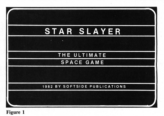
To boldy announce our title, we'll use the large text mode of GRAPHICS 2 followed by a smaller descriptive phrase in GRAPHICS 1 and a small copyright notice at the bottom in GRAPHICS 0. Our scratch pad for figuring the Display List would look something like Figure 1.
The first step in "hand assembling" the Display List is to find out which of the mode line types being used requires the most memory. This is determined by looking up (in figure 2) the memory requirements for each BASIC GRAPHICS mode that corresponds to the mode line being used in the display. Looking at GRAPHICS 0 through GRAPHICS 2 we find that GRAPHICS 0 requires the most memory. Therefore, when we build the display list from BASIC, we will start by initializing a GRAPHICS 0 Display List and then modifying it.
| GR. MODE | TYPE | RESOLUTION | MEM SIZE |
|---|---|---|---|
| 0 | Text | 40 x 24 | 960 |
| 1 | Text | 20 x 20 | 560 |
| 2 | Text | 20 x 10 | 360 |
| 3 | Graphics | 40 x 20 | 360 |
| 4 | Graphics | 80 x 40 | 560 |
| 5 | Graphics | 80 x 40 | 960 |
| 6 | Graphics | 160 x 80 | 1760 |
| 7 | Graphics | 160 x 80 | 3360 |
| 8 | Graphics | 320 x 160 | 6560 |
| 17 | Text | 20 x 24 | 480 |
| 18 | Text | 20 x 12 | 240 |
| 19 | Graphics | 40 x 24 | 240 |
| 20 | Graphics | 80 x 48 | 480 |
| 21 | Graphics | 80 x 48 | 960 |
| 22 | Graphics | 160 x 96 | 1920 |
| 23 | Graphics | 160 x 96 | 3840 |
| 24 | Graphics | 320 x 192 | 7680 |
After the general position of each mode line is sketched, the next problem to overcome is the adjustment of the number of scan lines to 192 and the adjustment of the number of'mode lines used in each portion of the redefined Display List so that the display is balanced out. If we were to simply modify each line we needed to redefine, an interesting and somewhat irritating problem would arise.
When we type GRAPHICS 0 at the start of the program, the Operating System (OS) generates a Display List of 24 mode lines consisting of 40 bytes per display line. A mode line, in this case, is the ANTlC code for a screen line. A display line is the visible physical line which the OS sees as starting at multiples of the number of bytes per mode line.
For example: The first byte of display line four in GRAPHICS 0 is located at the beginning of screen memory plus a number equal to the sum of the number of bytes per mode line (40) times the display line number. This means that in order to write to the first byte of line four, the OS must write to the start of screen memory plus 160 (40*4). Now if we should change the length of line one to be GRAPHICS 2 (20 bytes long), the OS would still write to screen memory plus 160 (it doesn't know that we have removed 20 bytes from line one). But that location will be 20 bytes past the real location of the first byte of line four. The OS would be looking for 40 bytes of data for mode line one whereas ANTIC only needed 20. This would cause the OS to think that the next 20 bytes following the 20 GRAPHICS 2 bytes are still part of the same display line.
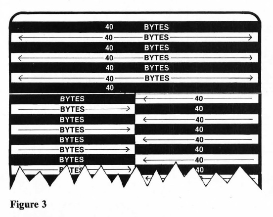
In effect, half of the next mode line on the display is actually the previous display line wrapping around to the bottom. In order to write to the second mode line of the display (still a GRAPHICS 0 line), we actually have to write to the middle of the first display line. But this is only the beginning of the problem. Every time we try to print at an X-coordinate of zero following the modified mode lines, the text appears to be indented 20 BYTES (halfway) into the display line. Figure 3 shows graphically what actually happens. Display line one stretches halfway into mode line two, and every display line after that is offset by 20 bytes.
One way to correct this problem is to add enough extra mode lines of different lengths to bring the start of each line back to the left edge. For example: If we modify two mode lines to be GRAPHICS 2, then all the display lines after the GRAPHICS 2 mode lines will be all right. This is because, by using two lines, the sum of the bytes required for the GRAPHICS 2 lines comes out to be 40. The lines following the GRAPHICS 2 lines are shifted another 20 bytes, and the screen lines up _again. The display line numbers will be offset by the number of extra lines required to align the display. Since we have inserted an extra GRAPHICS 2 line into the Display List, all the following display line numbers will be one LESS than they would normally be. The OS thinks that lines one and two are all part of line one. Therefore, display line four will appear to be line three to the OS. ANTIC, however, requires separate mode line bytes for each line on the display, but when we PRINT/ PLOT to the screen, it's the OS we have to accomodate, not ANTIC.
As long as redefinition is kept in multiples of the base GRAPHICS mode (i.e., the one used as the base which is modified), then normal screen/video commands will work. Of course nothing is THAT easy. In order to POSITION and PRINT there are some special things to do, as we'll see later.
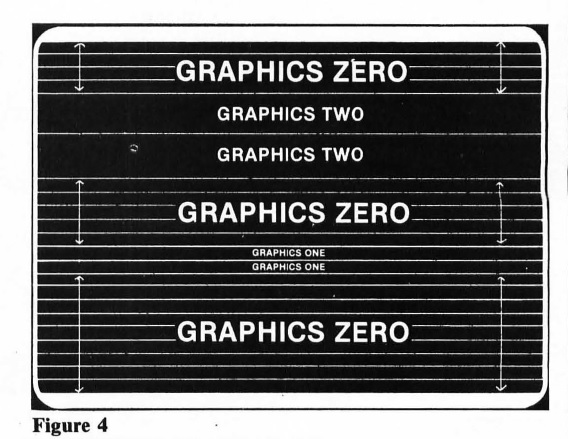
Now we should write down the number of bytes per mode line on our scratch pad, and next to that the number of scan lines each mode line takes (see figure 1 last month). GRAPHICS 2 requires 20 bytes per line at 16 scan lines per mode line. GRAPHICS 1 requires 20 bytes per line at 8 scan lines per mode line. GRAPHICS 0 requires 40 bytes per line at 8 scan lines per mode line. By putting 2 lines of GRAPHICS 2 at the top of the display, and 2 lines of GRAPHICS 1 in the middle, all GRAPHICS 0 lines start at the left edge where they belong. The problem now is that when we add up all 24 GRAPHICS 0 mode lines (including the ones we will modify) the scan line count comes out to be 208 - too many. We can solve this by removing excess GRAPHICS 0 lines from the bottom of the Display List. Taking out two GRAPHICS 0 lines will adjust the scan line count to be 192.
Figure 4 is a completed outline of the custom Display List. All that remains now is to actually modify the standard BASIC GRAPHICS 0 Display List. It would be a good exercise to translate, on paper, what the Display List should look like, and then look at Figure 5. Compare this to the GRAPHICS 0 Display List (Figure 2 last month).
| DL BYTE NO. | BYTE VALUE | MODE TYPE |
|---|---|---|
| 1 | 112 | Blank |
| 2 | 112 | Blank |
| 3 | 112 | Blank |
| 4 | 66 | Graphics 0 w/LMS option |
| 5 | nn | Least significant byte of screen memory |
| 6 | nn | Most significant byte of screen memory |
| 7 | 2 | Graphics 0 |
| 8 | 2 | Graphics 0 |
| 9 | 2 | Graphics 0 |
| 10 | 7 | Graphics 2 |
| 11 | 7 | Graphics 2 |
| 12 | 2 | Graphics 0 |
| 13 | 2 | Graphics 0 |
| 14 | 2 | Graphics 0 |
| 15 | 2 | Graphics 0 |
| 16 | 2 | Graphics 0 |
| 17 | 6 | Graphics 1 |
| 18 | 6 | Graphics 1 |
| 19 | 2 | Graphics 0 |
| 20 | 2 | Graphics 0 |
| 21 | 2 | Graphics 0 |
| 22 | 2 | Graphics 0 |
| 23 | 2 | Graphics 0 |
| 24 | 2 | Graphics 0 |
| 25 | 2 | Graphics 0 |
| 26 | 2 | Graphics 0 |
| 27 | 2 | Graphics 0 |
| 28 | 65 | Jump w/WVB option |
| 29 | nn | Least significant byte of DL |
| 30 | nn | Most significant byte of DL |
What we want to do now is to generate a GRAPHICS 0 Display List and modify it to look like Figure 5. We start by executing a GRAPHICS 0 command and PEEKing into memory to find out where the OS has put the Display List. The following lines of BASIC will accomplish this:
10 GRAPHICS 0:POKE 752,1
20 DL=PEEK(560)+PEEK(561)*256
After these lines have been executed, the variable DL will point to the first byte of the Display List. Since the first three bytes of any Display List are blank mode line instructions (see last month), I usually offset the pointer by four. The variable DL will then point to the location of the first byte of screen data. As an extra benefit, this will make display line number one equal to DL-1 and display lines two and up equal to DL+2, +3, and so on. This seems confusing at first, but there is a twisted sort of logic involved if you look hard enough.
Next, we pick the Display List byte that approximately corresponds to the location drawn on our scratch pad. In this case, line five in GRAPHICS 0 is the closest. Then we must calculate the position of the byte to modify, and POKE it with the ANTIC code that corresponds to the GRAPHICS mode we want to use. If you look at Figure 1 from the last installment, you will find that GRAPHICS 2 is known to ANTIC as a mode number 7 byte. By POKEing this into the location we calculated, we will have modified one line on the screen. To defeat the previously discussed conflict that arises from GRAPHICS 2 requiring only 20 bytes of screen data, we can also POKE the next location with 7, and the screen will line up again. We can now add these lines to the program:
30 DL=DL+4
40 POKE DL+5,7:POKE DL+6,7
Display line 12 is the nearest approximation of the next set of lines to be modified. GRAPHICS 1 is listed as being equivalent to ANTIC mode 6. Adding line 50 takes care of the subtitle line:
50 POKE DL+12,6:POKE DL+13,6
Now that the Display List has been modified, all that remains to complete the Display List is to shorten it to 192 scan lines long. All we really have to do is to write the 3 bytes required to end a normal Display List into memory two bytes lower than the location they already occupy. This eliminates two lines of GRAPHICS 0 and brings the scan line count to 192. If you remember, the bytes required to end a Display List are a 65, followed by the memory location of the start of the Display List in LSB, MSB order. These two bytes are conveniently stored for us at memory locations 560 and 561. Lines 60 and 70 will shorten the display and complete the modifications:
60 POKE DL+28,65:POKE DL+29,PEEK(560)
70 POKE DL+30,PEEK(561):? CHR$(125)
When all of the above lines have been typed in and the program has been RUN, a normal display will .appear on the screen with the exception that two sections of the display are black. This is because the modified lines are operating in a GRAPHICS mode that uses a different color than the background. This can be eliminated by making both background colors the same. Add line number 80 shown below; it will reset the colors so that the screen is uniform:
80 SETCOLOR 2,9,0:SETCOLOR 4,9,0
The only things remaining for our title page are the PRINT statements to write the display. Remembering that the POSITION statement is now slightly out of kilter because of the GRAPHICS 1 and 2 mode lines, the only way to write to the screen effectively is to make a guess. The guess should be based on the screen format, and repeated, by trial and error, until text appears where it is required. We know that the display is now two lines shorter than before (we eliminated them to bring the scan line count to normal). We also know that the matched set of GRAPHICS 1 and 2 lines are considered a pair of single lines by the OS. It turns out that line four is the start of the GRAPHICS 2 line and line ten is the GRAPHICS 1 line. The following lines print to the screen, at a position derived by trial and error, to center the text and display:
90 POSITION 4,4:? "STAR SLAYER"
100 POSITION 4,10:? "the ultimate":POSITION 25,10:? "space game"
110 POSITION 4,17:? "(C) 1982 - SoftSide Publications"
Pay particular attention to line 100. When the program is RUN, the words "SPACE GAME" are on the line following the words "THE ULTIMATE", but the POSITION statement is pointing to the same line. As mentioned before, the OS now thinks that the second line is part of the first. Line 100 could be rewritten to read:
100 POSITION 4,10:? "the ultimate space game"
120 FOR X=1 TO 4
130 FOR Y=255 TO 100 STEP -2.5
140 SOUND 0,Y,10,8:SOUND 1,351-Y,10,8
150 NEXT Y:NEXT X
160 SOUND 2,201,10,8:SOUND 3,253,10,8
170 GOTO 170
Now that the title page is done, the screen will stay modified either until another GRAPHICS command is executed or until SYSTEM RESET is pressed. Try some experimenting with the display. Type on the modified lines in combinations of inverse and lowercase - the effects can be fascinating. Try using different codes when POKEing the Display List. Or try POKEing different locations. It's up to you. You can learn more by experimenting with your own ideas than from a hundred articles explaining how it works. If you should discover something interesting, write in and tell us about it so we can let others know. If we all pitch in for the common good and the general improvement of ATARI® software, we can all benefit.
Next time we'll get into some of the other types of Display Lists and the problems which arise when using them from BASIC. As always, I'm more than anxious to hear comments and advice from any reader of SoftSide.