Editor's note: Unless you have read the issue #35 installment of "Exploring the Atari Frontier", the information presented here will be somewhat confusing. In addition, I'm assuming you have read all the past installments listed below:
| No. | SoftSide | Title |
|---|---|---|
| #1 | May 1982 | ANTIC and the Display List: Part 1 |
| #2 | Issue #31 | ANTIC and the Display List: Part 2 |
| #3 | Issue #34 | ANTIC and the Display List: Part 3 |
| #4 | Issue #35 | Display List Interrupts |
| #5 | Issue #39 | GTIA Part 1: A Brilliant Idea |
In issue #39, we talked about the new and exciting features of Atari's GTIA upgrade package. We showed that GTIA produces sophisticated and colorful displays straight from BASIC. In fact, BASIC tradeoffs and lack of programmer imagination cause GTIA's only limitations. You cannot overcome the latter (without a lot of effort), but you can defeat the former by programming in Machine Language which enhances the operation of BASIC in many ways. Routines can range from a simple USR call, to driver programs that enable features built into the Atari, but not normally available from BASIC. ANTIC falls into the latter category. Its simple instructions work with GTIA (or CTlA) to create all the standard BASIC screen displays commonly known as GRAPHICS 0-8. It also has many subfeatures unnecessary for most BASIC applications. ANTIC's most interesting feature is a topic all too familiar to old Frontier readers - Display List Interrupts (DLIs). The DLI allows you to change the GTIA display while the screen is being drawn. This creates some truly colorful displays.
The display list of any GTIA graphics mode may confuse you at first. To familiarize yourself with the display lists for GRAPHICS 9 through 11, you must first look at GRAPHICS 8. The ANTIC code for a GRAPHICS 8 mode line is 15 decimal (0F hex). You can be sure that when a 15 decimal appears in the display list, it will be a GRAPHICS 8 mode line. Or can you? If you look at the GRAPHICS 9 display list, you find a GRAPHICS 8 mode line! In fact, all of the new GTIA graphics modes consist of GRAPHICS 8 mode lines. The reason is simple. The values from zero to 255 already have definitions in the ANTIC language. Since there was no room to add more instructions for three new graphics modes, an existing mode was chosen to represent anyone of four distinct graphics modes. That answers the question of why, but how can one common graphics mode be four unique graphics modes at the same time?
Look at Table 1. We will use some of these locations to solve the mystery of GTIA. The first significant location in the table is DINDEX. The Operating System (OS) uses this location to store the current screen graphics mode. BASIC also uses the location to calculate the position of data sent to the screen. For example, when DINDEX is set to zero, BASIC assumes a screen of 40 by 24 text characters. If DINDEX is set to four, BASIC assumes a screen of 80 by 40 color graphics pixels.
| Dec | Hex | Name | Description |
|---|---|---|---|
| 00087 | $0057 | DINDEX | Screen graphics mode index. |
| 00512 | $0200 | VDSLST | LSB of DLI jump vector. |
| 00513 | $0201 | VDSLST | MSB of DLI jump vector. |
| 00559 | $022F | SDMCTL | DMA control register (shadow). |
| 00560 | $0230 | SDLSTL | LSB of display list memory location. |
| 00561 | $0231 | SDLSTH | MSB of display list memory location. |
| 0623 | $026F | GPRIOR | Screen priority register (shadow). |
| 0704 | $02C0 | PCOLR0 | Player color register 0 (shadow). |
| 0705 | $02C1 | PCOLR1 | Player color register 1 (shadow). |
| 0706 | $02C2 | PCOLR2 | Player color register 2 (shadow). |
| 0707 | $02C3 | PCOLR3 | Player color register 3 (shadow). |
| 0708 | $02C4 | COLOR0 | Color register 0 (shadow). |
| 0709 | $02C5 | COLOR1 | Color register 1 (shadow). |
| 0710 | $02C6 | COLOR2 | Color register 2 (shadow). |
| 0711 | $02C7 | COLOR3 | Color register 3 (shadow). |
| 0712 | $02C8 | COLOR4 | Color register 4 (shadow). |
| 53266 | $D012 | COLPM0 | Player color register 0 (hardware). |
| 53267 | $D013 | COLPM1 | Player color register 1 (hardware). |
| 53268 | $D014 | COLPM2 | Player color register 2 (hardware). |
| 53269 | $D015 | COLPM3 | Player color register 3 (hardware). |
| 53270 | $D016 | COLPF0 | Color register 0 (hardware). |
| 53271 | $D017 | COLPF1 | Color register 1 (hardware). |
| 53272 | $D018 | COLPF2 | Color register 2 (hardware). |
| 53273 | $D019 | COLPF3 | Color register 3 (hardware). |
| 53274 | $D01A | COLBK | Color register 4 (hardware). |
| 53275 | $D01B | PRIOR | Screen priority register (hardware). |
| 54280 | $D40A | WSYNC | Wait for vertical sync. |
| 54286 | $D40E | NMIEN | Non maskable interrupt enable. |
If we now execute a GRAPHICS 8 statement, logically DINDEX should contain an eight. If we try GRAPHICS 9, DINDEX contains a nine. The logical conclusion is that the only difference between a GRAPHICS 8 screen and a GRAPHICS 9 screen is that DINDEX reflects the actual GRAPHICS mode used. This conclusion is wrong.
ANTIC and GTIA must work together. Neither can accomplish much when operating separately. Moreover, they must communicate quickly because of the amount of work to be done while the screen is being drawn. To achieve such a high information transfer rate, you must store the information inside the chips themselves. To facilitate direct input to the chips, certain memory addresses are hardwired to the chip's storage registers. These locations are positioned high up in RAM, and are commonly referred to by Atari as hardware registers, to distinguish them from the temporary registers in RAM known as shadow registers.
A certain magical union exists between the shadow and hardware registers. The data stored in shadow registers is written periodically to the hardware registers during the Vertical Blank Interrupt (VBI). In this way, ANTIC and GTIA are constantly updated on changes occurring in the operating environment. For example: Location COLOR4 (see Table 1) contains the current screen background color. Let's say a value of 144 is held there. From BASIC, a statement such as SETCOLOR 4,0,4 is executed and the computed color value of four is placed into COLOR4. (see issue #39 for a discussion of POKE vs SETCOLOR). The hardware still thinks the background color is 144. During the VBI, the OS takes the value in COLOR4 and puts it into the hardware register COLBK. The result changes the background color. Why go through all that when you could have put the color value directly into the hardware register? If you were to do that, you would lose an enormous amount of flexibility.
Look at DLIs, for example: their function mandates the use of this feature. VBIs occur between each screen, but DLIs can be set for almost every line of the screen. When a DLI places a new color value into the hardware register, the effect is immediate. From that screen line downward, the color changes. At the end of the screen, the VBI occurs and restores the color value contained in the shadow memory. By using many DLIs you can change every color on the screen as it is drawn.
Getting back to DINDEX - here is a memory location just for the benefit of the OS for screen formatting. It is not a shadow register, so the information it contains is useless to ANTIC. It is apparent that something else controls the "GTIA effect." After examining all the clues, I deduced that either DINDEX really was a shadow register and I would have to find its corresponding hardware register, or that GTIA worked by magic, and I should call Atari to find out how and why. After exhausting the first possibility, I tried the second. A helpful genius at Atari gave me the information I needed, but the answer surprised me.
The answer to how ANTIC discriminates between GRAPHICS 8 and the new GTIA modes is found in a register used primarily for Player/Missile (PM) graphics manipulation. The twin pair of locations known as GPRIOR and PRIOR (see Table 1) is the source of the GTIA's actions. In a CTIA graphics mode (zero to eight), the two most significant bits (bits six and seven) of these registers are set to zero. Whenever a GTIA graphics mode is selected, however, bits six and seven are set to another state.
Table 2 compares all the BASIC graphic modes using ANTIC mode line fifteen. The only apparent difference in GRAPHICS 9-11 and 24 is pixel size. GRAPHICS 8 takes less memory only because it has a text window at the bottom. The values listed in Table 2 for GPRIOR equate as follows: GRAPHICS 8 and 24, bits six and seven equal zero; GRAPHICS 9, bit six equals one and bit seven equals zero; GRAPHICS 10, bit six equals zero and bit seven equals one; GRAPHICS 11, bits six and seven equal one. GPRIOR is the shadow register located in RAM. Writing a value here sets the default GTIA graphics mode for the entire screen. PRIOR is the hardware counterpart, which you can change with a DLI to modify the screen as it is drawn.
| Mode | Resolution | Memory | GPRIOR | DINDEX |
|---|---|---|---|---|
| 8 | 320 x 160 | 6560 | 0 | 8 |
| 9 | 80 x 192 | 7680 | 64 | 9 |
| 10 | 80 x 192 | 7680 | 128 | 10 |
| 11 | 80 x 192 | 7680 | 192 | 11 |
| 24 | 320 x 192 | 7680 | 0 | 8 |
ANTIC is totally innocent in the GTIA conspiracy. To ANTIC, graphics modes eight to eleven are identical. In an indirect way, DINDEX is responsible for how ANTIC and GTIA coordinate their operations. When the OS finds a GTIA mode value (nine to eleven) stored in DINDEX, it modifies data going to the screen in a special way. By shifting and transforming bits, the OS puts a special interpretation of screen data into memory for GTIA's benefit. GTIA takes an ANTIC mode fifteen and alters its appearance to form the new graphics mode displays. GTIA works on data received from ANTIC, and actually modifies its appearance. It thinks that all data coming to it while GPRIOR/PRIOR are selected is a new form of text display. To prove this, try the following test. Set up a normal GRAPHICS 0 screen (i.e. type GRAPHICS 0). Now POKE GPRIOR (623 decimal) with the values in Table 2. With GRAPHICS 8, the display is normal. However, when the values of GRAPHICS 9-11 are POKEd, the screen reverts to GTIA color graphics! Try executing normal commands like LIST, PRINT, and so on. Now we know how to get a GTIA mode, but how can we use this information with DLIs? This is where the excitement really begins.
This time, I have three different demos which require some explanation. Refer now to Program Listing 1a, Program Listing 1b, and Figure 1. Program Listing la is the BASIC program to create the demo; Program Listing 1b is the Machine Language DLI routine, and Figure 1 is the modified display list. The first demo is called Palette, and displays all 128 standard Atari colors.
| Byte# | Value | Mode type |
|---|---|---|
| 1 | 112 | Blank |
| 2 | 112 | Blank |
| 3 | 112 | Blank |
| 4 | 79 | Graphics 8 w/LMS option |
| 5 | nn | LSB of screen memory |
| 6 | nn | MSB of screen memory |
| 7 | 15 | Graphics 8 |
| . | . | . |
| . | . | . |
| . | . | . |
| 27 | 15 | Graphics 8 |
| 28 | 143 | Graphics 8 w/DLI option |
| 29 | 15 | Graphics 8 |
| . | . | . |
| . | . | . |
| . | . | . |
| 51 | 15 | Graphics 8 |
| 52 | 143 | Graphics 8 w/DLI option |
| 53 | 15 | Graphics 8 |
| . | . | . |
| . | . | . |
| . | . | . |
| 75 | 15 | Graphics 8 |
| 76 | 143 | Graphics 8 w/DLI option |
| 77 | 15 | Graphics 8 |
| . | . | . |
| . | . | . |
| . | . | . |
| 99 | 15 | Graphics 8 |
| 100 | 207 | Graphics 8 w/LMS & DLI options |
| 101 | nn | LSB of screen memory |
| 102 | nn | MSB of screen memory |
| 103 | 15 | Graphics 8 |
| . | . | . |
| . | . | . |
| . | . | . |
| 125 | 15 | Graphics 8 |
| 126 | 143 | Graphics 8 w/DLI option |
| 127 | 15 | Graphics 8 |
| . | . | . |
| . | . | . |
| . | . | . |
| 149 | 15 | Graphics 8 |
| 150 | 143 | Graphics 8 w/DLI option |
| 151 | 15 | Graphics 8 |
| . | . | . |
| . | . | . |
| . | . | . |
| 173 | 15 | Graphics 8 |
| 174 | 143 | Graphics 8 w/DLI option |
| 175 | 15 | Graphics 8 |
| . | . | . |
| . | . | . |
| . | . | . |
| 199 | 15 | Graphics 8 |
| 200 | 65 | Jump w/WVB option |
| 201 | nn | LSB of DL in memory |
| 202 | nn | MSB ofDL in memory |
100 GRAPHICS 11:POKE 712,0:POKE 559,0
110 DL=PEEK(560)+PEEK(561)*256+4
120 FOR X=0 TO 79:COLOR INT(X/5)
130 PLOT X,0:DRAWTO Y,191:NEXT X
140 COLOR 0:FOR X=0 TO 15:PLOT X*5,0
150 DRAWTO X*5,191:NEXT X
160 FOR X=0 TO 7:FOR Y=20 TO 23
170 PLOT 0,X*24+Y:DRAWTO 79,X*24+Y
180 NEXT Y:NEXT X
190 FOR X=23 TO 71 STEP 24
200 POKE DL+X,143:NEXT X
210 FOR X=121 TO 190 STEP 24
220 POKE DL+X,143:NEXT X
230 POKE 512,128:POKE 513,6:M=1663
240 M=M+1:READ D:IF D=999 THEN 260
250 POKE M,D:GOTO 240
260 POKE DL+95,207:POKE 54286,192
270 POKE 559,34:GOTO 270
300 DATA 216,72,173,153,6,24,105,2
310 DATA 141,10,212,141,26,208,201
320 DATA 14,208,2,169,0,141,153,6
330 DATA 104,64,0,999
               1000        .OR $0680
               1010        .TA $4000
               1020 *
               1030 * DEFINE SYSTEM EQUATES
               1040 *
D40A-          1050 WSYNC  .ED $D40A  ;WAIT VERTICAL SYNC REGISTER.
D01A-          1060 COLBK  .EQ $DOIA  ;GTIA BACKGROUND COLOR REGISTER.
               1070 *
               1080 * START OF GTIA HANDLER
               1090 *
0680- D8       1100 START CLD         ;CLEAR THE DECIMAL MODE.
0681- 48       1110 PHA               ;SAVE THE 'A' REGISTER ON STACK.
0682- AD 99 06 1120 LDA STORE         ;GET COLOR VALUE INTO THE
0685- 18       1130 CLC               ; A RESISTER, CLEAR THE
0686- 69 02    1140 ADC $$02          ; CARRY FLAG AND ADD TWO.
0688- 8D 0A D4 1150 STA WSYNC         ;WAIT FOR VERTICAL SYNC.
068B- 8D 1A D0 1160 STA COLBK         ;CHANGE BACKGROUND COLOR.
068E- C9 0E    1170 CMP 41$0E         ;TEST FOR LAST LEGAL COLOR.
0690- D0 02    1180 BNE OUT           ;SKIP IF SO.
0692- A9 00    1190 LDA 000           ;RESET COLOR REGISTER POINTER
0694- 8D 99 06 1200 OUT STA STORE     ;AND SAVE FOR NEXT DLI.
0697- 68       1210 PLA               ;RESTORE THE 'A' REGISTER.
0698- 40       1220 RTI               ;RETURN FROM INTERRUPT.
1230 *
1240 * COLOR POINTER
1250 *
0699- 00       1260 STORE  .HS 00
| Byte# | Value | Mode type |
|---|---|---|
| 1 | 112 | Blank |
| 2 | 112 | Blank |
| 3 | 112 | Blank |
| 4 | 71 | Graphics 2 w/LMS option |
| 5 | nn | LSB of screen memory |
| 6 | nn | MSB of screen memory |
| 7 | 134 | Graphics 1 w/DLI option |
| 8 | 2 | Graphics 0 |
| 9 | 130 | Graphics 0 w/DLI option |
| 10 | 15 | Graphics 8 |
| . | . | . |
| . | . | . |
| . | . | . |
| 59 | 15 | Graphics 8 |
| 60 | 143 | Graphics 8 w/DLI option |
| 61 | 15 | Graphics 8 |
| . | . | . |
| . | . | . |
| . | . | . |
| 99 | 15 | Graphics 8 |
| 100 | 79 | Graphics 8 w/LMS option |
| 101 | nn | LSB of screen memory |
| 102 | nn | MSB of screen memory |
| 103 | 15 | Graphics 8 |
| . | . | . |
| . | . | . |
| . | . | . |
| 110 | 15 | Graphics 8 |
| 111 | 143 | Graphics 8 w/DLI option |
| 112 | 15 | Graphics 8 |
| 113 | 143 | Graphics 8 w/DLI option |
| 144 | 15 | Graphics 8 |
| . | . | . |
| . | . | . |
| . | . | . |
| 137 | 15 | Graphics 8 |
| 138 | 143 | Graphics 8 w/DLI option |
| 139 | 15 | Graphics 8 |
| . | . | . |
| . | . | . |
| . | . | . |
| 163 | 15 | Graphics 8 |
| 164 | 65 | Jump w/WVB option |
| 165 | nn | LSB of DL in memory |
| 166 | nn | MSB ofDL in memory |
100 GRAPHICS 24:POKE 712,0:POKE 559,0
110 DL=PEEK(560)+PEEK(561)*256+4
120 POKE DL-1,71:POKE DL+2,134
130 POKE DL+3,2:POKE DL+4,130
140 FOR X=5 TO 95:POKE DL+X,15:NEXT X:FOR X=98 TO 158:POKE DL+X,15:NEXT X:POKE DL+95,79:POKE DL+159,65:M=1663
150 POKE DL+160,PEEK(560):POKE DL+161,PEEK(561):POKE DL+55,143:POKE DL+106,143:POKE DL+108,143:POKE DL+132,143
160 M=M+1:READ D:IF D=999 THEN 500
170 POKE M,D:GOTO 160
300 DATA 216,72,138,72,174,195,6,189
310 DATA 183,6,201,0,208,12,189,189
320 DATA 6,141,10,212,141,24,208,76
330 DATA 163,6,189,189,6,141,10,212
340 DATA 141,26,208,189,183,6,141,27
350 DATA 208,232,224,6,208,2,162,0
360 DATA 142,195,6,104,170,104,64
400 DATA 0,64,192,192,0,0
410 DATA 0,0,8,0,0,148,0,999
500 POKE 512,128:POKE 513,6
510 POKE 54286,192:POKE 559,34
520 POKE 87,0:POSITION 0,0:? "     gtia DEMO"," softside issue #40":? "    EXPLORING THE ATARI FRONTIER"
530 POKE 752,1:? "    GTIA DISPLAY LIST INTERRUPTS":POKE 87,9:FOR Y=3 TO 52:COLOR INT(Y/4):PLOT 0,Y:DRAWTO 79,Y
540 NEXT Y:POKE 87,11:FOR Y=53 TO 102:COLOR INT((Y-53)/3):PLOT 0,Y:DRAWTO 79,Y:NEXT Y
550 POKE 87,8:Y=99:A=0:FOR X=15 TO 319 STEP 64:GOSUB 580:NEXT X
560 COLOR 1:PLOT 0,143:DRAWTO 319,143:FOR X=0 TO 315:PLOT X+2,-SIN(X/25)*12+143:NEXT X
570 GOTO 570
580 COLOR 1:FOR ZA=0 TO 10:FOR AZ=0 TO ZA STEP 2:PLOT X+15+AZ,Y-ZA+25:PLOT X+15-AZ,Y-ZA+25:NEXT AZ:NEXT ZA
590 FOR ZA=11 TO 15:FOR AZ=0 TO 10 STEP 2:PLOT X+15+AZ,Y-ZA+25:PLOT X+15-AZ,Y-ZA+25:NEXT AZ:NEXT ZA
600 Z=-2:FOR ZA=16 TO 18:Z=Z+2:FOR AZ=Z TO 8-Z STEP 2:PLOT X+15+AZ,Y-ZA+25:PLOT X+15-AZ,Y-ZA+25:NEXT AZ:NEXT ZA
610 RETURN
               1000        .OR $0680
               1010        .TA $4000
               1020 *
               1030 * DEFINE SYSTEM EQUATES
               1040 *
D01B-          1050 PRIOR  .EQ $0018 ;GTIA MODE ENABLE REGISTER.
D40A-          1060 WSYNC  .EQ $040A ;WAIT VERTICAL SYNC REGISTER.
D01B-          1070 COLPF2 .EQ $0018 ;CTIA BACKGROUND COLOR REGISTER.
D018-          1080 COLBK  .EQ $001A ;GTIA BACKGROUND COLOR REGISTER.
               1090 *
               1100 * START OF GTIA HANDLER
               1110 *
0680- D8       1120 START  CLD         ;CLEAR THE DECIMAL MODE.
0681- 48       1130        PHA         ;SAVE THE 'A' REGISTER ON STACK.
0682- 8A       1140        TXA         ;TRANSFER 'X' TO 'A' AND
0683- 48       1150        PHA         ; AND SAVE IT ON THE STACK ALSO.
0684- AE C3 06 1160        LDX STORE   ;GET COLOR TABLE OFFSET POINTER.
0687- BD B7 06 1170        LDA MODE,X  ;GET CTIA/GTIA STATUS MODE.
068A- C9 00    1180        CMP #$00    ;CHECK FOR CTIA MODE.
068C- D0 0C    1190        BNE GTIA    ;60 TO GTIA ROUTINE IF NOT.
068E- BD BD 06 1200 CTIA   LDA COLOR,X ;GET COLOR TO REPLACE.
0691- 8D 0A D4 1210        STA WSYNC   ;WAIT FOR VERTICAL SYNC.
0694- 8D 18 D0 1220        STA COLPF2  ;STORE NEW COLOR IN REGISTER.
0697- 4C A3 06 1230        JMP CHECK   ;JUMP TO CHECK ROUTINE.
069A- BD BD 06 1240 GTIA   LDA COLOR,X ;GET COLOR TO REPLACE.
069D- 8D 0A D4 1250        STA WSYNC   ;WAIT FOR VERTICAL SYNC.
06A0- 80 1A D0 1260        STA COLBK   ;STORE NEW COLOR IN REGISTER.
06A3- BD B7 06 1270 CHECK  LDA MODE,X  ;GET CTIA/GTIA MODE STATUS.
06A6- 8D 1B D0 1280        STA PRIOR   ;STORE IT INTO THE REGISTER.
06A9- E8       1290        INX         ;BUMP COLOR TABLE POINTER.
06AA- E0 06    1300        CPX #$06    ;CHECK FOR END OF TABLE.
06AC- D0 02    1310        BNE OUT     ;IF NOT, JUMP OUT.
06AE- A2 00    1320        LDX #$00    ;RESTORE COLOR TABLE POINTER.
06B0- 8E C3 06 1330 OUT    STX STORE   ;SAVE CURRENT POINTER FOR
06B3- 68       1340        PLA         ; NEXT DLI, GET AND RESTORE
06B4- AA       1350        TAX         ; THE 'X' REGISTER FROM THE
06B5- 68       1360        PLA         ; STACK, RESTORE THE 'A'
06B6- 40       1370        RTI         ; REGISTER AND EXIT.
               1380 *
               1390 * DLI COLOR TABLE AND POINTER 1400 *
06B7- 00 40 CO
06BA- C0 00 00 1410 MODE   .HS 0040C0C00000
06BD- 00 00 08
06C0- 00 00 94 1420 COLOR  .HS 000008000094
06C3- 00       1430 STORE  .HS 00
| Byte# | Value | Mode type |
|---|---|---|
| 1 | 112 | Blank |
| 2 | 112 | Blank |
| 3 | 112 | Blank |
| 4 | 79 | Graphics 8 w/LMS option |
| 5 | nn | LSB of screen memory |
| 6 | nn | MSB of screen memory |
| 7 | 15 | Graphics 8 |
| . | . | . |
| . | . | . |
| . | . | . |
| 15 | 15 | Graphics 8 |
| 16 | 143 | Graphics 8 w/DLI option |
| 17 | 15 | Graphics 8 |
| . | . | . |
| . | . | . |
| . | . | . |
| 27 | 15 | Graphics 8 |
| 28 | 143 | Graphics 8 w/DLI option |
| 29 | 15 | Graphics 8 |
| . | . | . |
| . | . | . |
| . | . | . |
| 39 | 15 | Graphics 8 |
| 40 | 143 | Graphics 8 w/DLI option |
| 41 | 15 | Graphics 8 |
| . | . | . |
| . | . | . |
| . | . | . |
| 51 | 15 | Graphics 8 |
| 52 | 143 | Graphics 8 w/DLI option |
| 53 | 15 | Graphics 8 |
| . | . | . |
| . | . | . |
| . | . | . |
| 63 | 15 | Graphics 8 |
| 64 | 143 | Graphics 8 w/DLI option |
| 65 | 15 | Graphics 8 |
| . | . | . |
| . | . | . |
| . | . | . |
| 75 | 15 | Graphics 8 |
| 76 | 143 | Graphics 8 w/DLI option |
| 77 | 15 | Graphics 8 |
| . | . | . |
| . | . | . |
| . | . | . |
| 87 | 15 | Graphics 8 |
| 88 | 143 | Graphics 8 w/DLI option |
| 89 | 15 | Graphics 8 |
| . | . | . |
| . | . | . |
| . | . | . |
| 99 | 15 | Graphics 8 |
| 100 | 207 | Graphics 8 w/LMS & DLI option |
| 101 | nn | LSB of screen memory |
| 102 | nn | MSB of screen memory |
| 103 | 15 | Graphics 8 |
| . | . | . |
| . | . | . |
| . | . | . |
| 113 | 15 | Graphics 8 |
| 114 | 143 | Graphics 8 w/DLI option |
| 115 | 15 | Graphics 8 |
| . | . | . |
| . | . | . |
| . | . | . |
| 125 | 15 | Graphics 8 |
| 126 | 143 | Graphics 8 w/DLI option |
| 127 | 15 | Graphics 8 |
| . | . | . |
| . | . | . |
| . | . | . |
| 137 | 15 | Graphics 8 |
| 138 | 143 | Graphics 8 w/DLI option |
| 139 | 15 | Graphics 8 |
| . | . | . |
| . | . | . |
| . | . | . |
| 149 | 15 | Graphics 8 |
| 150 | 143 | Graphics 8 w/DLI option |
| 151 | 15 | Graphics 8 |
| . | . | . |
| . | . | . |
| . | . | . |
| 161 | 15 | Graphics 8 |
| 162 | 143 | Graphics 8 w/DLI option |
| 163 | 15 | Graphics 8 |
| . | . | . |
| . | . | . |
| . | . | . |
| 173 | 15 | Graphics 8 |
| 174 | 143 | Graphics 8 w/DLI option |
| 175 | 15 | Graphics 8 |
| . | . | . |
| . | . | . |
| . | . | . |
| 185 | 15 | Graphics 8 |
| 186 | 143 | Graphics 8 w/DLI option |
| 187 | 15 | Graphics 8 |
| . | . | . |
| . | . | . |
| . | . | . |
| 197 | 15 | Graphics 8 |
| 198 | 143 | Graphics 8 w/DLI option |
| 199 | 15 | Graphics 8 |
| 200 | 65 | Jump w/WVB option |
| 201 | nn | LSB of DL in memory |
| 202 | nn | MSB of DL in memory |
100 GRAPHICS 9:POKE 712,0:POKE 559,0
110 DL=PEEK(560)+PEEK(561)*256+4
120 FOR X=0 TO 79:COLOR X
130 PLOT X,0:DRAWTO X,191:NEXT X
140 FOR X=11 TO 83 STEP 12
150 POKE DL+X,143:NEXT X
160 FOR X=109 TO 190 STEP 12
170 POKE DL+X,143:NEXT X
180 POKE 512,128:POKE 513,6:M=1663
190 M=M+1:READ D:IF D=999 THEN 210
200 POKE M,D:GOTO 190
210 POKE DL+95,207:POKE 54286,192
220 POKE 559,34:GOTO 220
300 DATA 216,72,173,153,6,141,10,212
310 DATA 24,105,16,141,26,208,201,240
320 DATA 208,2,169,0,141,153,6,104
330 DATA 64,0,999
               1000       .OR $0680
               1010       .TA $4000
               1020 *
               1030 * DEFINE SYSTEM EQUATES
               1040 *
D40A-          1050 WSYNC .EQ $D40A ;WAIT VERTICAL SYNC REGISTER.
D01A-          1060 COLBK .EQ $D01A ;STIA BACKGROUND COLOR REGISTER.
               1070 *
               1080 * START OF GTIA HANDLER
               1090 *
0680- D8       1100 START CLD       ;CLEAR THE DECIMAL MODE.
0681- 48       1110       PHA       ;SAVE THE 'A' REGISTER ON STACK.
0682- AD 99 06 1120       LDA STORE ;GET COLOR VALUE INTO THE
0685- 18       1130       CLC       ; 'A' REGISTER, CLEAR THE
0686- 69 10    1140       ADC #$10  ; CARRY FLAG AND ADD TEN.
0688- 80 0A D4 1150       STA WSYNC ;WAIT FOR VERTICAL SYNC.
068B- 8D 1A D0 1160       STA COLBK ;CHANGE BACKGROUND COLOR.
068E- C9 F0    1170       CMP #$F0  ;TEST FOR LAST LEGAL COLOR.
0690- D0 02    1180       BNE OUT   ;SKIP IF SO.
0692- A9 00    1190       LDA #$00  ;RESET COLOR REGISTER POINTER.
0694- 8D 99 06 1200 OUT   STA STORE ;SAVE FOR NEXT DLI.
0697- 68       1210       PLA       ;RESTORE THE 'A' REGISTER.
0698- 40       1220       RTI       ;RETURN FROM INTERRUPT.
               1230 *
               1240 * COLOR POINTER
               1250 *
0699- 00       1260 STORE .HS 00
In Figure 1 you will notice several DLI instructions. These correspond to the changes of color down the screen. The PEEKs and POKEs contained in Program Listing la are all defined in Table 1, and should be fairly familiar. The DLI routines are tricky, however. We'll take them one at a time.
The listings show us a few interesting things. Program Listing la uses GRAPHICS 11 as a base. Stepping the luminance levels progressively down the screen will display all 128 colors. The DLI routine holds in memory a temporary value that is incremented by two every time a DLI occurs, and puts this value in the location that controls luminance levels in GRAPHICS 11. Program Listing 1b shows us a few EQuates for WSYNC and COLBK. The first actual 6502 instruction we confront is a CLD (Clear Decimal Mode). This is a new instruction in our DLI routines, because previous DLI examples have not needed it. What it does and why are another story in themselves, but to make a long story short: Atari constantly pops in and out of the 6502 decimal mode. When the DLI occurs, you can't tell what mode you are in. Since this is the first time a DLI routine has used an ADC instruction,this is the first time CLD was needed.
The rest of this DLI routine is fairly straight forward. The decimal mode is cleared, the luminance value retrieved and incremented by two, WSYNC is activated to allow proper timing for the STA instruction that follows, a quick comparison is made to the limit for luminance value allowed, and the adjusted value is saved for later. The registers used were saved on the stack and removed after the routine was finished. I realize this is a very brief explanation of its function. If you are still confused, reread the previous installments.
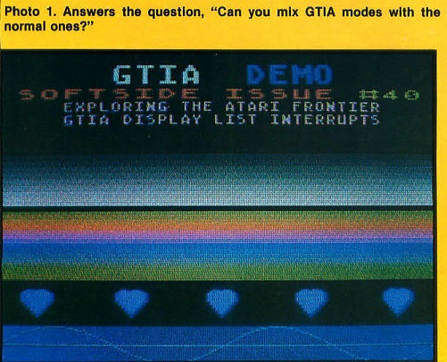
Program Listing 2a, Program Listing 2b, Figure 2, and Photo 1 refer to the next demo which I wrote to answer the theoretical question: "Can you mix (GTIA modes) with the normal ones?" Yes you can, but it's much harder than I thought.
Program Listing 2a creates a mixed display of GRAPHICS 0, 1, 2, 8, 9, and 11. Table 1 explains the many POKES. The DLI routine again needs explanation. This time we need a routine to put a table of colors in the correct locations as each DLI is processed. A pointer indicates the current table entry. Another table tells GTIA when ANTIC mode fifteen means something other than GRAPHICS 8. The simplest way is to place into the table the correct bit values for the graphics mode being displayed, and then POKE these values into PRIOR.
Starting with the EQuates, we find a list of standard names found in Table 1. Then comes the mandatory CLD instruction and a general SAVE of all registers used. The table offset pointer is retrieved and the GTIA mode status is checked. If the mode is GTIA, processing branches to a special GTIA handler routine; otherwise the routine falls through to a CTIA processing routine. In either case, the color is stuffed into the corresponding color register for the associated CTIA/GTIA mode and a branch to a check routine is executed. This routine only determines when the table pointer should wrap around and then saves the pointer for the next DLI. It looks easy, but discovering how to do it for the first time is difficult. I recommend that you look at Program Listing 2a.
The routines to draw the display provide intrigue for the curious. Pay particular attention to the POKEs in relation to where the information is placed. See if you can discover what goes on using the tables, listings, and figures. It pays to experiment here. This entire installment was researched and prepared by trial and error. I had no idea how GTIA worked or how it could be used with DLIs. Experimenting worked for me; why not try it yourself?
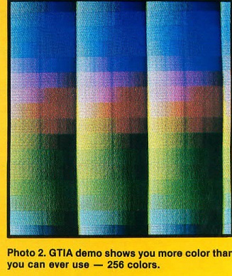
CTIA owners will find Program Listing 3a, Program Listing 3b, and Figure 3 of particular interest. For those who stilI haven't upgraded to GTIA, we provide Photo 2. It's true that any CTIA machine can display 128 colors, but only a GTIA displays 256. This demo proves you really can get more colors than you would ever need in a program. Visually, it appears to be three columns of sixteen colored disks. Note the shading effect, as if a light were shining on the columns. The effect was created using GRAPHICS 9 to make three columns of increasing luminance, and DLIs to alternate the colors down the screen.
The DLI routine for this example is similar to the routine in the first demo. The main difference is that we increment the pointer by 10 hex (16 decimal) so that the color is incremented and the luminance is unchanged. Look through the listing and the figures until everything is clear. A few POKEs in the listings will come in handy when you write your own programs. One not listed, but of great importance, is POKE 54286,64. This POKE turns off the DLI effect.
Whenever the DLI is enabled, system time is at a premium, and timing conflicts might occur. When these arise, the DLI always gets last priority. The OS key click routine interferes with the DLI, making the display jitter slightly when you press a key during an INPUT or GET. The effect is insignificant, and you can overcome it by PEEKing the keyboard or using joystick input. The only major problem occurs during external peripheral I/O. When you output to the printer, save to disk, or even load a program from cassette, the DLI suffers. This is a good time to use POKE 54286,64. By turning off the interrupts, you can preserve the current state of your display list and re-enable it afterwards by POKEing 54286 with 192. Depending on the complexity of your display, you may optionally choose to disable the screen display, as well. If you try Program Listing 2 without DLIs enabled, you may cringe. Just POKE 559,0. This shuts off the display so you can't see the mess left by a disabled DLI. To get the screen back, POKE 559,34. This location is for PM graphics and the value of 34 assumes that PMs are not used.
I want to thank Dave Welch of Atari Inc., who helped me so much with this column. It's nice to know that Atari provides people like Dave to assist in the development of outside software, or in this case, a column.
The words DLI and ANTIC will never appear in Frontier again. I promise. We've turned the final page of the final chapter of ANTIC and the display list. We will take a poll and the topic with the most votes will be our next feature series. Until then, have fun Exploring The Atari Frontier!