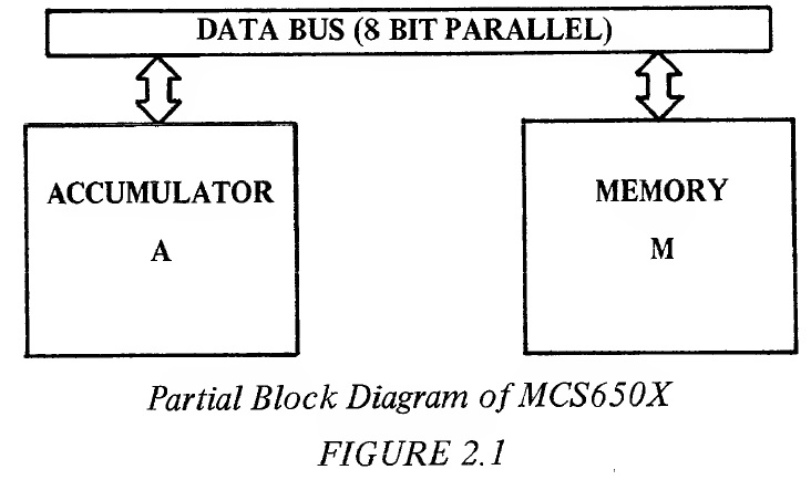
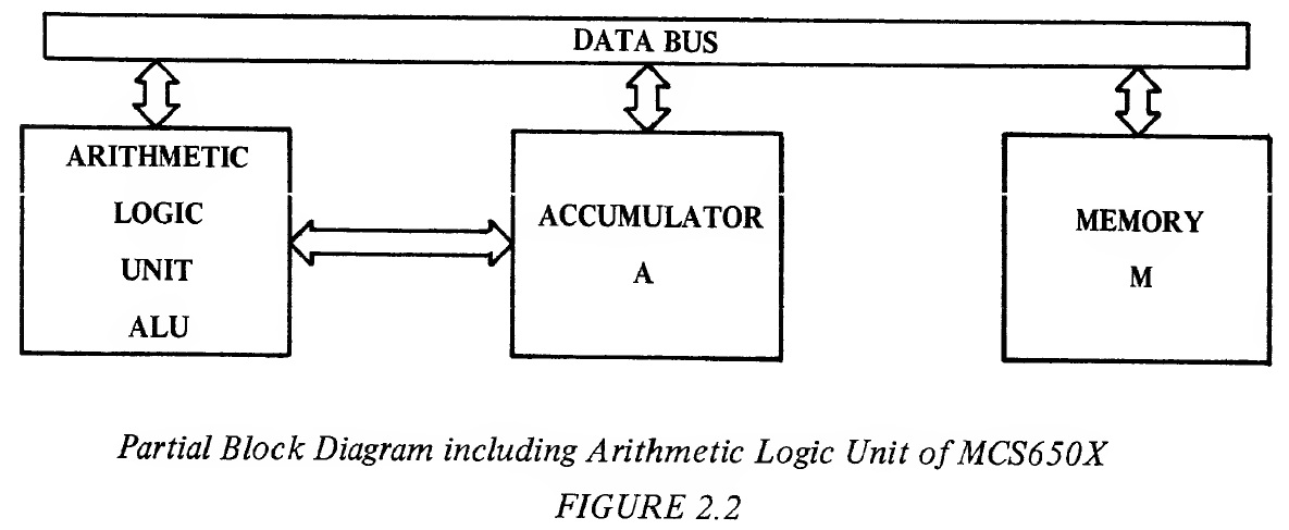
The only operation of the data bus is to transfer data between memory and the processor's internal registers such as the accumulator. Figure 2.1 displays the basic communication between the accumulator, A, and the memory, M, through the use of 8 bi-directional data lines called the data bus. 2.1 THE ACCUMULATOR The accumulator is a register in which data is kept on which operations are performed. All operations between memory locations must be communicated through the accumulator or one of the auxiliary index registers. The accumulator is used as a temporary storage in moving data from one memory location to another. Therefore, the first use for the accumulator (A) is just in transferring data from memory to the accumulator or from the accumulator to memory. One can bring data into the accumulator, perform operations such as AND/OR on it, test the results of those operations, set new bits into it, or transfer it back out to the outside world. It serves as an interim storage for a series of operations such as adding 2 values together; where one of them is loaded into the accumulator, the second one added to it, and the results stored in the accumulator. The accumulator really acts as two functions: 1) It is one of the primary storage points for the machine; 2) It is the point at which intermediate results are normally stored. 2.1.1 LDA--Load Accumulator with Memory When instruction LDA is executed by the microprocessor, data is transferred from memory to the accumulator and stored in the accumulator. Rather than continuing to give a word picture of the operation, introduced will be the symbolic representation M ^ A, where the arrow means "transfer to." Therefore the LDA instruction symbolic representation is read, "memory transferred to the accumulator." LDA affects the contents of the accumulator, does not affect the carry or overflow flags; sets the zero flag if the accumulator is zero as a result of the LDA, otherwise resets the zero flag; sets the negative flag if bit 7 of the accumulator is a 1, otherwise resets the negative flag. Although yet to be developed is the concept of addressing modes, for reference purpose, LDA is a "Group One" instruction and has all of the major addressing modes of the machine available to it as stated in Appendix A. These addressing modes include Immediate; Absolute; Zero Page; Absolute, X; Absolute, Y; Zero Page,X; Indexed Indirect; and Indirect Indexed. 2.1.2 STA--Store Accumulator in Memory This instruction transfers the contents of the accumulator to memory. The symbolic representation for this instruction is A → M. This instruction affects none of the flags in the processor status register and does not affect the accumulator. It is a "Group One" instruction and has the following addressing modes available to it: Absolute; Zero Page; Absolute, X; Absolute, Y; Zero Page,X; Indexed Indirect; and Indirect Indexed. 2.2 THE ARITHMETIC UNIT One of the functions to be expected from any computer is the ability to compute or perform arithmetic operations. Even in a simple control problem, one often finds it useful to add 2 numbers in order to determine that a value has been reached, or subtract 2 numbers to calculate a new value which must be obtained. In addition, many problems involve some rudimentary form of decimal or binary arithmetic: certainly many applications of the microprocessor will involve both. The MCS650X has an 8-bit arithmetic unit which interfaces to the accumulator as shown in Figure 2.2
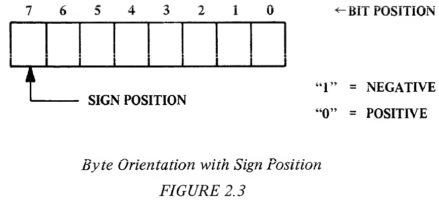
The arithmetic unit is composed of several major parts. The most important of these is the circuitry necessary to perform a two's complement add of 8-bit parallel values and generate an 8 parallel bit binary result plus a carry. A review of binary and binary coded decimal (BCD) arithmetic is presented in Appendix H. However, a quick review of the concept of "carry" is in order. The largest range than can be represented in an 8-bit number is 256 with values ranging between and 255. If we add any 2 numbers which result in a sum which is greater than 255, we represent the result with a ninth bit plus the 8 bits of the excess over 255. The ninth bit is called "carry." 2.2.1 ADC--Add Memory to Accumulator with Carry This instruction adds the value of memory and carry from the previous operation to the value of the accumulator and stores the result in the accumulator. The symbolic representation for this instruction is A + M + C → A. This instruction affects the accumulator; sets the carry flag when the sum of a binary add exceeds 255 or when the sum of a decimal add exceeds 99, otherwise carry is reset. The overflow flag is set when the sign or bit 7 is changed due to the result exceeding +127 or -128, otherwise overflow is reset. The negative flag is set if the accumulator result contains bit 7 on, otherwise the negative flag is reset. The zero flag is set if the accumulator result is 0, otherwise the zero flag is reset. It is a "Group One" instruction and has the following addressing modes: Immediate; Absolute; Zero Page; Absolute, X; Absolute, Y; Zero Page,X; Indexed Indirect; and Indirect Indexed. The ninth bit of the result is stored in the carry flag and the remaining 8 bits reside in the accumulator. The carry flag can be thought of as a flag bit which is remote from, the accumulator itself but which is directly affected by accumulator operations as though it were a ninth bit in the accumulator. The primary reason for not viewing the carry bit as merely a ninth bit in the accumulator is that one has program control over its state by being able to set (to "1") or clear (to "0") the bit and, of course, it is not part of the 8-bit accumulator in data transfer operations. Examples employing the Add with Carry operation follow. Example 2.1: Add 2 numbers with carry; no carry generation 0000 1101 13 = (A)* 1101 0011 211 = (M)* __ 1 1 = CARRY Carry = /0/ 1110 0001 225 = (A) *(A) and (M) refer to the "contents" of the accumulator and "contents" of memory respectively. Example 2.2: Add 2 numbers with carry; carry generation 1111 1110 254 = (A) 0000 0110 6 = (M) __ 1 1 = CARRY Carry = /1/ 0000 0101 5 = (A) While the accumulator contains "5," the carry flag signals the user that the result exceeded 255 and, therefore, the result can be properly interpreted as 256 + 5 = 261. 2.2.1.0 Multiple Precision Addition To perform the addition of 2 numbers, one issues to the microprocessor an ADC instruction which adds the memory and the accumulator and stores the results in the accumulator with the carry bit going set if the results exceeded 255. To add numbers which had significantly higher value than 255, it would be necessary to represent these numbers by a series of serial 8-bit numbers. With the 16 bits in 2 serial 8-bit numbers, it is possible to represent binary numbers of greater than 65,000 in value. In order to add two 16-bit numbers together and thus accomplish double precision addition, one first loads the lowest byte of one number into the accumulator, clears the carry flag and then adds the second number to the first number in the accumulator using the ADC command. One would then store this result into another memory location using the STA command. The carry flag would now represent the carry from the lowest byte to the highest byte. One could then load the high order byte of the first number, add with carry again to the high value of the second number, and store the result in the high order byte of the result. Thus, it can be seen that the carry allows us to perform as much precision arithmetic as is necessary. The example listing below displays the commands used to execute the addition of two 16-bit numbers. Example 2.3: Adding two 16-bit numbers High Order Byte Low Order Byte First Number H1 L1 Second Number H2 L2 Result of Addition H3 L3 LDA L1 Load low order byte, first number CLC Clear carry flag (carry = 0) ADC L2 Add LI to low order byte, second number STA L3 Store result in memory, carry flag is still set if set in ADC operation LDA H1 Load high order byte, first number ADC H2 Add H1 and carry value from first ADC operation to high order byte, second number STA H3 Store result in memory In this example it was necessary to clear the carry flag before starting the add instruction. This, of course, means that commands exist that set and clear the carry flag allowing for addition without values generated from the prior operation. One could also, at the end of the program, check to see if the result exceeded 16 bits by testing the carry flag. Exactly how one alters and tests flags will be discussed in the Flag and Branches Section. The examples below display the concept of carry from the addition of the low order bytes. Example 2.4: Add two 16-bit numbers, no carry from low order add 0000 0001 0000 0010 258 0001 0000 0001 0000 4112 Add low order bytes: (clear carry) 0000 0010 (A) __ 0001 0000 (M) Carry = /0/ 0001 0010 (A) Add high order bytes (carry = 0): 0000 0001 (A) 0001 0000 (M) __ 0 CARRY Carry = /0/ 0001 0001 (A) Result = 0001 0001 0001 0010 = 4370 Example 2.5: Add two 16-bit numbers, with carry from low order add 0000 0001 1000 0000 384 0000 0000 1000 0000 128 Add low order bytes: (clear carry) 1000 0000 (A) __ 1000 0000 (M) Carry = /1/ 0000 0000 (A) Add high order bytes: (carry = 1) 0000 0001 (A) 0000 0000 (M) __ 1 CARRY Carry = /0/ 0000 0010 (A) Result = 0000 0010 0000 0000 = 512 2.2.1.1 Signed Arithmetic It is possible to look at the add operation and the way data is represented in memory in a different way. If, in the 16-bit problem (Examples 2.4 and 2.5), one were working with 15 bits of precision (in other words, 15 bits of valid data) plus 1 bit of sign (0 for positive and 1 for negative) , it would be possible to perform signed binary arithmetic without changing the adder, but by merely changing the way the results are interpreted. In order to facilitate this concept, the microprocessor has the ability to represent positive or negative numbers by means of a sign flag which will be discussed at length in Section 3.7. In the MCS650X family, bit 7 is the sign position bit. This means that the highest order byte in a series of bytes should have the sign in the eighth position. If, for simplicity, one talks about signed 8-bit numbers, it would mean that one was allowed only 128 combinations of each sign because that is the most that can be represented in 7 bits, with the eighth bit or the highest bit reserved for the sign position.
In the following examples of signed arithmetic it should be noted that operations are occurring on a 7-bit field of numbers and that any carry generated out of that field will reside in the eighth bit--not in the carry flag discussed during the add operations. The generation of a carry out of the field is the same as when adding two 8-bit numbers, except for the fact that the normal carry flag does not correctly represent the fact that the field has been exceeded. This is because the true carry from adding the two 7-bit numbers resides in the sign bit position. Therefore, the carry flag has no real meaning. Instead, there is a separate flag, the overflow flag, used to indicate when a carry from 7 bits has occurred and allows the user to write correction programs. In each example, the negative numbers are in two's complement form. Also included in each result will be the status of the carry and overflow flags. The overflow flag is set whenever the sign bit (bit 7) is changed as a result of the operation. Example 2.6: Add 2 positive numbers with no overflow 0000 0101 +5 (A) __ 0000 0111 +7 (M) Carry = /0/ 0000 0010 +12 (A) __ Overflow = /0/ "0" in bit 7 indicates positive result. Note that both the carry and overflow flag remain cleared. Example 2.7: Add 2 positive numbers with overflow 0111 1111 +127 (A) __ 0000 0010 + 2 (M) Carry = /0/ 1000 0001 "-127" (A) __ Overflow = /1/ "1" in bit 7 indicates negative result and the two's complement of the result is 127; however, the overflow flag is set indicating the allowable range was exceeded in the addition. Therefore, examination of the overflow indicated that the result was in fact not negative but that the bit 7 position represented an overflow beyond the value of 127 . Hence the user is flagged of an incorrect result and a correction routine (program) must follow. Example 2.8: Add positive and negative number with positive result 0000 0101 +5 (A) __ 1111 1101 -3 (M) Carry = /1/ 0000 0010 +2 (A) __ Overflow = /0/ "0" in bit 7 indicates positive result. (Recall that though the carry flag is set, it has no meaning in signed operations.) Example 2.9: Add positive and negative number with negative result 0000 0101 +5 (A) __ 1111 1001 -7 (M) Carry = /0/ 1111 1110 -2 (A) __ Overflow = /0/ "1" in bit 7 indicates negative result. Example 2.10: Add 2 negative numbers without overflow 1111 1011 -5 (A) __ 1111 1001 -7 (M) Carry = /1/ 1111 0100 -12 (A) __ Overflow = /0/ "1" in bit 7 indicates negative result. Example 2.11: Add 2 negative numbers with overflow 1011 1110 -66 (A) __ 1011 1111 -65 (M) Carry = /1/ 0111 1101 "+125" (A) __ Overflow = /1/ "0" indicates positive result, but the overflow flag is set indicating that the allowable range was exceeded in the operation. Without the overflow indication, the result would be interpreted as +125. The overflow, however, indicated that the result was negative and exceeded the value -128. Hence the user is flagged of an incorrect result, indicating the need for a correction routine. 2.2.1.2 Decimal Addition There is a way for the user to organize data for decimal operations. The MOS Technology, Inc. MCS650X microprocessors have a modified adder which allows the user to represent his numbers as two 4-bit binary coded decimals (BCD) numbers packed into a single byte. This is a unique feature of the MCS650X family in that the operation in the following example can be performed. Example 2.12: Decimal addition CLC Clear Carry Flag SED Set Decimal Mode LDA 0111 1001 79 ADC 0001 0100 +14 STA 1001 0011 93 The microprocessor adder has the unique capability of performing real time correction to the normal expected binary result without any direct interference from the programmer. Other popular microprocessors require a separate instruction (Decimal Adjust) which corrects the direct binary result of the arithmetic unit to obtain the same final results as are available on this microprocessor directly. In order to make the same arithmetic unit perform either as a binary adder or as a decimal adder, the user chooses the mode in which he is going to operate (either decimal or binary) by setting another flip-flop in the microprocessor called the decimal flag. As shown in this example, one not only initializes the adder by clearing the carry flag, but also puts the processor into decimal mode with the SED instruction. Even though this also requires 1 instruction, it is possible to put the machine in decimal mode once and perform many long strings of decimal numbers without further user intervention. The "Decimal Adjust" feature on other microprocessors requires programming subsequent to each binary operation. 2.2.1.3 Add Summary In summary, the basic arithmetic unit is a binary adder which, under control of the ADC command, performs binary arithmetic on the accumulator and data, storing the result in the accumulator. Depending on the way the user looks at the data which is presented to the adder and the results which are obtained from it, the user can determine whether or not the result exceeds 255 binary or 99 decimal; he can perform precision arithmetic by use of the ninth bit or carry flag; he can control whether or not the microprocessor is a decimal adder by setting the decimal mode; and he can represent his numbers as signed binary numbers by analyzing other flags that are set in the machine. 2.2.2 SBC Subtract Memory from Accumulator with Borrow This instruction subtracts the value of memory and borrow from the value of the accumulator, using two's complement arithmetic, and stores the result in the accumulator. Borrow is defined as the carry flag complemented; therefore, a resultant carry flag indicates that a borrow has not occurred. The symbolic representation for this instruction is _ A - M - C → A. This instruction affects the accumulator. The carry flag is set if the result is greater than or equal to 0. The carry flag is reset when the result is less than 0, indicating a borrow. The overflow flag is set when the result exceeds +127 or -127, otherwise it is reset. The negative flag is set if the result in the accumulator has bit 7 on, otherwise it is reset. The Z flag is set if the result in the accumulator is 0, otherwise it is reset. It is a "Group One" instruction. It has addressing modes Immediate; Absolute; Zero Page; Absolute,X; Absolute, Y; Zero Page,X; Indexed Indirect; and Indirect Indexed. In a binary machine, the classical way to perform arithmetic is by using two's complement notation. In using two's complement notation, any subtraction operation becomes a sequence of bit complementations and additions. This reduces the complexity of the circuits required to perform a subtraction. When the SBC instruction is used in single precision subtraction, there will normally be no borrow; therefore, the programmer must set the carry flag, by using the SEC (Set carry to 1) instruction, before using the SBC instruction. The microprocessor adds the carry flag to the complemented memory data, resulting in a true two's complement form of the memory value with its sign inverted. Example 2.13: Subtract 2 numbers with borrow; positive result Assume a single precision subtraction where A contains 5 and M contains 3. The carry flag must be set to a 1 using the SEC instruction, thereby representing the no-borrow condition. The adder changes the sign of M by taking the two's complement of M. This involves complementing M and adding the carry bit. M = 3 0000 0011 Complemented M 1111 1100 Add C = 1 1 -M = -3 1111 1101 The adder adds A and the two's complement -M together. This operation occurs simultaneously with the complement operation. A = 5 0000 0101 Add -M = -3 1111 1101 Carry = /1/ 0000 0010 = +2 The presence of the carry flag after this operation indicates that No Borrow was required, therefore the result is +2. Example 2.14: Subtract 2 numbers with borrow; negative result Assume a single precision subtraction where A contains 5 and M contains 6. Set the carry flag to a 1 with SEC to indicate No Borrow. M = 6 0000 0110 Complemented M 1111 1001 Add C = 1 1 -M = -6 1111 1010 A = 5 0000 0101 Add -M = -6 1111 1010 Carry = /0/ 1111 1111 = -1 The absence of the carry flag after this operation indicates that a borrow was required, therefore the result is a -1 in two's complement form. The absolute (unsigned) result in straight binary could be obtained by taking the two's complement of this number. 2.2.2.0 Multiple Precision Subtraction Double precision subtraction is implemented in a fashion similar to addition. An example for subtracting a 16-bit number and storing the result follows: Example 2.15: Subtracting two 16-bit numbers High Order Byte Low Order Byte First Number H1 L1 Second Number H2 L2 Result of Subtraction H3 L3 SEC Set Carry LDA L1 Load Low Order Byte, First Number SBC L2 Subtract with Borrow, Low Order Byte of Second Number from L1 STA L3 Store Result in Memory LDA H1 Load High Order Byte, First Number SBC H2 Subtract with Borrow, High Order Byte of Second Number from H1 STA H3 Store Result in Memory Example 2.16: Subtract in double precision format; positive result Assume a double precision subtraction where 255 is to be subtracted from 512 for an example. Since there has been no borrow coming into this subtraction operation, the carry flag must be set. Following are the 2 numbers in binary form: High Order Byte Low Order Byte A field = 512 0000 0010 0000 0000 M field = 255 0000 0000 1111 1111 Since the adder can only operate on single byte numbers, the programmer must operate on the low order bytes first. M = 1111 1111 Complemented M = 0000 0000 Add C = 1 1 -M 0000 0001 A = 0000 0000 Add -M = 0000 0001 Carry = /0/ 0000 0001 The carry is brought over to the subtract operation on the high order bytes. M = 0000 0000 Complemented M = 1111 1111 Add C = 0 0 -M 1111 1111 A = 0000 0010 Add -M = 1111 1111 Carry = /1/ 0000 0001 The result in binary form follows: Carry = /1/ 0000 0001 0000 0001 = +257 The presence of the carry flag after the highest order byte subtraction indicates that the entire number required No Borrow, therefore it is a positive number in straight binary form. Example 2.17: Subtract in double precision format; negative result Now assume a double precision subtraction where 512 is to be subtracted from 255. Again, since there has been no borrow coming into this subtraction operation, the carry flag must be set. Following are the two numbers in binary form: High Order Byte Low Order Byte A field = 255 0000 0000 1111 1111 M field = 512 0000 0010 0000 0000 Operating on the lower order byte: M = 0000 0000 _ M = 1111 1111 Add C = 1 1 Carry = /1/ 0000 0000 = -M A = 1111 1111 Add -M = /1/ 0000 0000 Carry = /1/ 1111 1111 The presence of the carry = 1 indicates no borrow. The carry is now brought over to the high order byte subtract operation: M = 0000 0010 _ M = 1111 1101 Add C = 1 1 1111 1110 _ A = 0000 0000 M + C = 1111 1110 Carry = /0/ 1111 1110 The result in binary form is: Carry = /0/ 1111 1110 1111 1111 = -257 Carry = /0/ indicates the presence of a borrow, therefore the number is negative and is in two's complement form. 2.2.2.1 Signed Arithmetic Signed numbers can be subtracted, using the SBC instruction, just as easily as they can be added. The microprocessor converts the numbers from memory to its two's complemented form and then adds it to the value of the accumulator just as it does in an unsigned subtract described in Section 2.2.2. The addition operation is identical to that described, and to the examples given in Section 2.2.1.1 It should be remembered that before using the SBC instruction, either signed or unsigned, the carry flag must be set to a 1 in order to indicate a no borrow condition. The resultant carry flag has no meaning after a signed arithmetic operation. 2.2.2.2 Decimal Subtract As indicated in the Section 2.2.1.2, it is possible to represent numbers as packed 4-bit BCD numbers. In this case, which is again unique to this microprocessor, it is possible to make the adder act as though it is a decimal adder. In this case, the function of the machine is one of correcting for the subtraction of positive numbers by complementing the number, setting the carry and performing binary arithmetic with an automatic correction at the time the result is stored in the accumulator. The unique capabilities of this adder give the results as shown in the next example. Example 2.18: Decimal Subtraction SED Set Decimal Mode SEC Set Carry Flag LDA 0100 0100 44 SBC 0010 1001 29 STA 0001 0101 15 By setting the decimal mode and setting the carry flag, one can subtract number 29 from number 44 with the results in the accumulator automatically being 15. As has been indicated, one can perform both addition and subtraction when the machine is set in decimal mode, treating the bytes to be added as unsigned, positive, binary coded digits. The carry flag in addition represents the case when the result in the number exceeded 99 and in subtraction the absence of the carry flag represents a true borrow situation. 2.2.3 Carry and Overflow During Arithmetic Operations It is necessary to set or reset the carry flag prior to the beginning of any arithmetic instruction. Because the carry flag is set or reset as a result of the arithmetic operation at the end of the loop, one can test the flag to determine whether or not a carry or a borrow occurred in the operation. By proper use of the overflow flag one can treat the high order bit of any set of bytes as a sign bit as long as the results of the negative numbers are carried in two's complement form. The microprocessor also sets the overflow flip-flop to indicate when a result larger than can be stored in a 7-bit field has occurred and when the resultant sign is incorrect. In binary arithmetic the carry flag set indicates results in excess of 256, and in decimal arithmetic indicates results in excess of 99. Although the input carry is very important to these operations, a simple rule is: set the carry flag prior to subtract; clear the carry flag prior to add. 2.2.4 Logical Operands In implementing a parallel binary adder there are several useful logic functions which are subsets of a binary add operation. In the MCS650X family, these subsets are used to implement the logical operands "AND," "OR," and "EOR" (Exclusive Or). These operations are used to test and control bit manipulations. 2.2.4.1 AND--Memory with Accumulator The AND instructions transfer the accumulator and memory to the adder which performs a bit-by-bit AND operation and stores the result back in the accumulator. This instruction affects the accumulator; sets the zero flag if the result in the accumulator is 0, otherwise resets the zero flag; sets the negative flag if the result in the accumulator has bit 7 on, otherwise resets the negative flag. This is symbolically represented by A ∧ M → A. AND is a "Group One" instruction having addressing modes of Immediate; Absolute; Zero Page; Absolute, X; Absolute, Y; Zero Page,X; Indexed Indirect; and Indirect Indexed. One of the uses for the AND operation is that of resetting a bit in memory. In the example below. Example 2.19: Clearing a bit with AND LDA 1100 X111, where X is 0 or 1 AND 1111 0111 STA 1100 0111 a byte is loaded into the accumulator and the AND instruction resets the accumulator bit 3 to 0. The accumulator is then stored back into memory, thereby resetting the bit. 2.2.4.2 ORA "OR" Memory with Accumulator The ORA instruction transfers the memory and the accumulator to the adder which performs a binary "OR" on a bit-by-bit basis and stores the result in the accumulator. This is indicated symbolically by A ∨ M → A. This instruction affects the accumulator; sets the zero flag if the result in the accumulator is 0, otherwise resets the zero flag; sets the negative flag if the result in the accumulator has bit 7 on, otherwise resets the negative flag. ORA is a "Group One" instruction. It has the addressing modes Immediate; Absolute; Zero Page; Absolute, X; Absolute, Y; Zero Page,X; Indexed Indirect; and Indirect Indexed. To set a bit, the OR instruction is used as shown below: Example 2.20: Setting a bit with OR LDA 1110 Xlll, where X is or 1 ORA 0000 1000 STA 1110 1111 2.2.4.3 EOR--"Exclusive OR" Memory with Accumulator The EOR instruction transfers the memory and the accumulator to the adder which performs a binary "EXCLUSIVE OR" on a bit-by-bit basis and stores the result in the accumulator. This is indicated symbolically by A