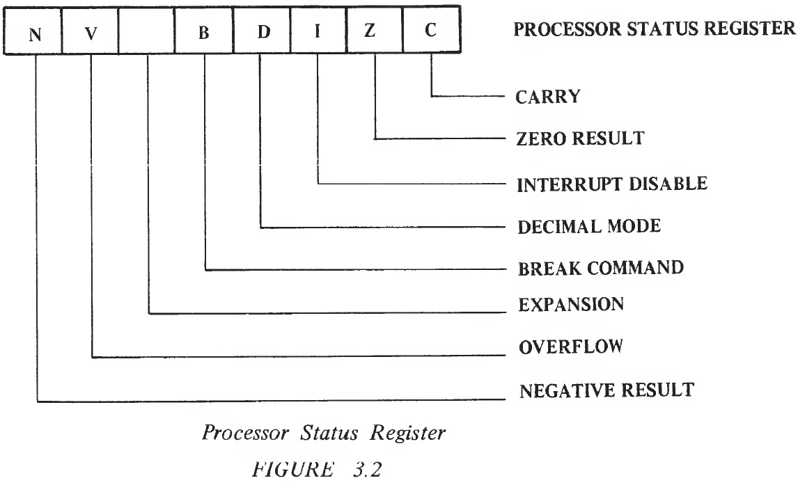
Each of the individual flags or bits has its own particular meaning in the microprocessor as defined in Figure 3.2.
3.0 CARRY FLAG (C) The carry bit which is modified as a result of specific arithmetic operations or by a set or clear carry command has been discussed previously, In the case of shift and rotate instruction, the carry bit is used as a ninth bit as it is in the arithmetic operation. The carry flag can be set or reset by the programmer. A SEC instruction will set and a CLC instruction will reset the carry flag. Operations which affect the carry are ADC, ASL, CLC, CMP, CPX, CPY, LSR, PLP, ROL, RTI, SBC, SEC. 3.0.1 SEC Set Carry Flag This instruction initializes the carry flag to a 1. This operation should normally precede a SBC loop. It is also useful when used with a ROL instruction to initialize a bit in memory to a 1. This instruction affects no registers in the microprocessor and no flags other than the carry flag which is set. SEC is a single-byte instruction and its addressing mode is Implied. 3.0.2 CLC--Clear Carry Flag This instruction initializes the carry flag to a 0. This operation should normally precede an ADC loop. It is also useful when used with a ROL instruction to clear a bit in memory. This instruction affects no registers in the microprocessor and no flags other than the carry flag which is reset. CLC is a single-byte instruction and its addressing mode is Implied. 3.1 ZERO FLAG (Z) This flag is automatically set by the microprocessor during any data movement or calculation operation when the 8 bits of results of the operation are 0. Therefore, the bit is on ("1") when the results are O, and off ("0") when the results are not equal to 0. The feature of the machine is similar to that of the PDP11 in the sense that operations which are decrementing index registers or memory locations have a built-in test for 0 as a result of decrementing to the 0 condition. It is also possible to test for condition immediately following load and other logical operations, as opposed to processors which have to do a test and branch instruction. The Z flag is not directly settable or resettable by an instruction but is affected by the following instructions: ADC, AND, ASL, BIT, CMP, CPY, CPX, DEC, DEX, DEY, EOR, INC, INX, INY, LDA, LDX, LDY, LSR, ORA, PLA, PLP, ROL, RTI, SBC, TAX, TAY, TXA, TYA. 3.2 INTERRUPT DISABLE (I) The interrupt disable is a flip-flop made use of by the programmer and by the microprocessor to control the operations of the interrupt request pin. A more detailed discussion of the effects of the interrupt disable are given in the discussion under interrupt control. However, the purpose of the interrupt disable is to disable the effects of the interrupt request pin. The interrupt disable, I, is set by the microprocessor during reset and interrupt commands. The I bit is reset by the CLI instruction or the PLP instruction, or at a return from interrupt in which the interrupt disable was reset prior to the interrupt. The interrupt flag may be set by the programmer using a SEI instruction and is cleared by the programmer by using a CLI instruction. Instructions which affect the interrupt disable are BRK, CLI, PLP, RTI and SEI. 3.2.1 SEI--Set Interrupt Disable This instruction initializes the interrupt disable to a 1. It is used to mask interrupt requests during system reset operations and during interrupt commands. It affects no registers in the microprocessor and no flags other than the interrupt disable which is set. SEI is a single-byte instruction and its addressing mode is Implied. 3.2.2 CLI--Clear Interrupt Disable This instruction initializes the interrupt disable to a 0. This allows the microprocessor to receive interrupts. It affects no registers in the microprocessor and no flags other than the interrupt disable which is cleared. CLI is a single-byte instruction and its addressing mode is Implied. 3.3 DECIMAL MODE FLAG (D) As discussed, the use of the decimal mode flag is to control whether or not the adder operates as a straight binary adder for add and subtract instructions or as a decimal adder for add and subtract instructions. The SED instruction sets the flag and the CLD instruction resets it. The only instructions which affect the decimal mode flag are CLD, PLP, RTI and SED, 3.3.1 SED--Set Decimal Mode This instruction sets the decimal mode flag D to a 1. This makes all subsequent ADC and SBC instructions operate as a decimal arithmetic operation. SED affects no registers in the microprocessor and no flags other than the decimal mode which is set to a 1. 3.3.2 CLD--Clear Decimal Mode This instruction sets the decimal mode flag to a 0. This causes all subsequent ADC and SBC instructions to operate as simple binary operations. CLD affects no registers in the microprocessor and no flags other than the decimal mode flag which is set to a 0. 3.4 BREAK COMMAND (B) The break command flag is set only by the microprocessor and is used to determine during an interrupt service sequence whether or not the interrupt was caused by BRK command or by a real interrupt. A more detailed discussion of BRK is in the interrupt section. This bit should be considered to have meaning only during an analysis of a normal interrupt sequence. There are no instructions which can set or which reset this bit. 3.5 EXPANSION BIT The next bit in the flag register is an unused bit. It is most likely that this bit will appear to be on when one is analyzing the bit pattern in the processor status register; however, no guarantee as to its state is made as this bit will be used in expanded versions of the microprocessor. 3.6 OVERFLOW (V) As discussed in the section on arithmetic operations, if one is to look at the binary arithmetic operations as signed binary operations, there needs to be some indication of the fact the result of the arithmetic operation has a greater value than could be contained in the 7 bits of the result. This bit is the overflow bit and during ADC and SBC instructions represents a status of an overflow into the sign position. The user who is not using signed arithmetic can totally ignore this flag during his programming; however, this flag has the same meaning as the carry to the user who is using signed binary numbers. It indicates that a sign correction routine must be used if this bit is on after an add or subtract using signed numbers. In addition to its use to monitor the validity of the sign bit in ADC and SBC instructions, the overflow flag in the MCS650X products is dramatically changed from PDP11 and the MC6800. In those systems the overflow flag was very carefully controlled so as to allow certain signed branches for analysis of signed numbers. These branches have been deleted from the MCS6500 series because of confusion and difficulty often associated with using them, and so therefore, the overflow flag is applicable only to the operation of ADC and SBC, and then only when using signed numbers. However, in order to maximize the effectiveness of this testable flag the BIT instruction which may be used to sample interface devices, allows the overflow flag to reflect the condition of bit 6 in the sampled field. During a BIT instruction the overflow flag is set equal to the content of the bit 6 on the data tested with BIT instruction. When used in this mode, the overflow has nothing to do with signed arithmetic but is just another sense bit for the microprocessor. Instructions which affect the V flag are ADC, BIT, CLV, PLP, RTI and SBC. On certain versions of the microprocessor the V bit will also be available for stimulus from the outside world. 3.6.1 CLV--Clear Overflow Flag This instruction clears the overflow flag to a 0. This command is used in conjunction with the set overflow pin which can change the state of the overflow flag with an external signal. CLV affects no registers in the microprocessor and no flags other than the overflow flag which is set to a 0. 3.6.2 Determination of Overflow To briefly recap the concept of overflow detection, one must understand that the machine signals an overflow based on the data entered to the operation and the final result. Since, with signed arithmetic, the range of numbers that be represented is +127 to -128, the overflow flag will never set when numbers of opposite sign are added, since their result will never exceed that range. The machine deals with this by recognizing that for any 2 positive numbers - the "bit 7" of each is a "0" and that for any arithmetic operation yielding a result less than or equal to +127, the resultant "bit 7" must be a "0." If it is a 1, the overflow flag is set. Similarly, when two negative numbers are added, the "bit 7" of each is a "1" and for any result yielding a value less than or equal to -128, the resultant "bit" must be a "1." If it is a 0, the overflow flag is set. Therefore, the machine recognizes by knowledge of the "bit 7" of each of the numbers to be added what the resultant "bit 7" must be in a non-overflow situation. If these conditions are not met, the overflow flag goes set. 3.7 NEGATIVE FLAG (N) As already discussed, one of the uses of the microprocessor is to perform arithmetic operations on signed numbers. To allow the user to readily sample the status of the sign bit (bit 7) , the N flag is set equal to bit 7 of the resulting value in all data movement and data arithmetic. This means, for instance, after a signed add one can determine the sign of the result by sampling the N flag directly rather than finding a way to isolate bit 7. Although signs were the primary purpose for which the N flag was intended, its usefulness far exceeds that of strictly a sign bit. Because of every operation including simple moves and add operations the N bit is equal to the status of bit 7 as a result of the operation; its primary use becomes that of an easily testable bit. Almost all single-bit instructions, all interrupts and all I/O status flags use bit 7 as a sense bit This allows the user to perform some type of memory access operation such as Load A followed by immediate conditional branch based on the status of bit 7 as reflected in the N flag. Like the Z bit, this flag is not settable or controllable by the programmer and represents the status of the last data movement operation. Instructions which affect the negative flag are ADC, AND, ASL, BIT, CMP, CPY, CPX, DEC, DEX, DEY, EOR, INC, INX, INY, LDA, LDX, LDY, LSR, ORA, PLA, PLP, ROL, BIT, SBC, TAX, TAY, TSX, TXA and TYA. 3.8 FLAG SUMMARY To summarize, the microprocessor treats a series of flags or status bits as a single register called the "P" or "Program Status" register. Some of these flags are controllable only by the programmer (such as the D flag) ; others are controllable by both the user program and microprocessor (such as the interrupt disable flag) . Some of them are set and reset by almost every processor operation, such as the N and Z flags. Each of these flags has its own meaning to the programmer at a particular point in time. When combined with the concept of conditional branches, they represent a powerful test and jump capability not normally found in a machine of this magnitude. Other than perhaps the carry flag which is used as part of the arithmetic instructions, the flags by themselves have relatively little meaning unless one has the ability to test them. For this purpose there is a series of conditional branch instructions designed into the machine.