MCS6500
Microcomputer Family
Programming Manual
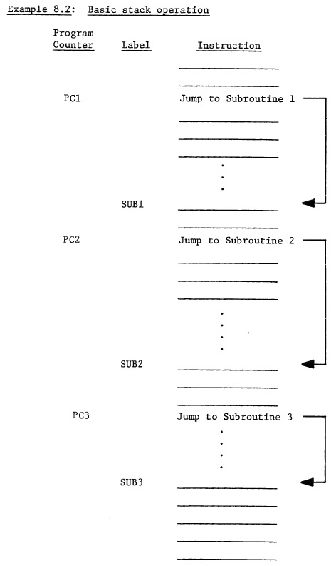
CHAPTER 8 STACK PROCESSING 8.0 INTRODUCTION TO STACK AND TO PUSH DOWN STACK CONCEPT In all of the discussions on addressing, it has been assumed that either the exact location or at least a relation to an exact location of a memory address was known. Although this is true in most of the programming for control applications, there are certain types of programming and applications which require that the basic program not be working with known memory locations but only with a known order for accessing memory. This type of programming is called re-entrant coding and is often used in servicing interrupts. To implement this type of addressing, the microprocessor maintains a separate address generator which is used by the program to access memory. This address generator uses a push down stack concept. Discussions of push down stacks are usually best stated considering that if one were given 3 cards, an ace, a king and a ten and were told that the order of cards was important and asked to lay them down on the table in the order in which they were given, ace first, the king on top of it and finally the ten, and then if they were retrieved, 1 card at a time, the ten is retrieved first even though it was put on last, the king is retrieved second, the ace retrieved last, even though it was put on first. The only commands needed to implement this operation are "put next card on stack" and "pull next card from the stack." The stack could be processing clubs and then go to diamonds and back to clubs. However, we know that while we are processing clubs, we will always find ten first, king second, etc. The hardware implementation of the ordered card stack which just described is a 16-bit counter, into which the address of a memory location is stored. This counter is called a "Stack Pointer." Every time data is to be pushed onto the stack, the stack pointer is put out on the address bus, data is written into the memory addressed by the stack pointer, and the stack pointer is decremented by 1 as may be seen in Example 8.1. Every time data is pulled from the stack, the stack pointer is incremented by 1. The stack pointer is put out on the address bus, and data is read from the memory location addressed by the stack pointer. This implementation using the stack pointer gives the effect of a push down stack which is program independent addressing. Example 8.1: Basic stack map for 3-deep JMP to subroutine sequence Stack Address Data 01FF PCH 1 01FE PCL 1 01FD PCH 2 01FC PCL 2 01FB PCH 3 01FA PCL 3 01F9 In the above example, the stack pointer starts out at OlFF. The stack pointer is used to store the first state of the program counter by storing the content of program counter high at OlFF and the content of program counter low at OlFE. The stack pointer would now be pointed at OlFD. The second time the store program count is performed, the program counter high number is stored on the stack at 01FD and the program counter low is stored at 01FC. The stack pointer would now be pointing at 01FB. The same procedure is used to store the third program counter. When data is taken from the stack, the PCL 3 will come first and the PCH 3 will come second just by adding 1 to the stack pointer before each memory read. The example above contains the program count for 3 successive jump and store operations where the jump transfers control to a subroutine and stores the value of the program counter onto the stack in order to remember to which address the program should return after completion of the subroutine. Following is an example of a program that would create the Example 8.1 stack operation.
This is known as subroutine nesting and is often encountered in solving complex control equations. To correctly use the stack for this type of operation requires a jump to subroutine and a return from subroutine instruction. 8.1 JSR - JUMP TO SUBROUTINE This instruction transfers control of the program counter to a subroutine location but leaves a return pointer on the stack to allow the user to return to perform the next instruction in the main program after the subroutine is complete. To accomplish this, JSR instruction stores the program counter address which points to the last byte of the jump instruction onto the stack using the stack pointer. The stack byte contains the program count high first, followed by program count low. The JSR then transfers the addresses following the jump instruction to the program counter low and the program counter high, thereby directing the program to begin at that new address. The symbolic notation for this is PC + 2+, (PC + 1) → PCL, (PC + 2) → PCH. The JSR instruction affects no flags, causes the stack pointer to be decremented by 2 and substitutes new values into the program counter low and the program counter high. The addressing mode for the JSR is always Absolute. Example 8.3 gives the details of a JSR instruction. Example 8.3: Illustration of JSR instruction Program Memory PC Data 0100 JSR 0101 ADL 0102 ADH Subroutine Stack Memory Stack Pointer Stack 01FD 01FE 02 01FF 01 External Internal Cycle Address Bus Data Bus Operations Operations 1 0100 OP CODE Fetch Finish Previous Instruction Operation; Increment PC to 0101 2 0101 New ADL Fetch Decode JSR; New ADL Increment PC to 0102 3 01FF Store ADL 4 01FF PCH Store PCH Hold ADL, Decrement S to 01FE 5 01FE PCL Store PCL Hold ADL, Decrement S to 01FD 6 0102 ADH Fetch ADH Store Stack Pointer 7 ADH, ADL New Fetch New ADL → PCL OP CODE OP CODE ADH → PCH * S denotes "Stack Pointer." In this example, it can be seen that during the first cycle the microprocessor fetches the JSR instruction. During the second cycle, address low for new program counter low is fetched. At the end of cycle 2, the microprocessor has decoded the JSR instruction and holds the address low in the microprocessor until the stack operations are complete. NOTE: The stack is always stored in Page 1 (Hex address 0100-01FF). The operation of the stack in the MCS650X microprocessor is such that the stack pointer is always left pointing at the next memory location into which data can be stored. In Example 8.3, the stack pointer is assumed to be at OlFF in the beginning and PC at location 0100. During the third cycle, the microprocessor puts the stack pointer onto the address lines and on the fourth writes the contents of the current value of the program counter high, 01, into the memory location indicated by the stack pointer address. During the time that the write is being accomplished, the stack pointer is being automatically decremented by 1 to 01FE. During the fifth cycle the PCL is stored in the next memory location with the stack pointer being automatically decremented. It should be noted that the program counter low, which is now stored in the stack, is pointing at the last address in the JSR sequence. This is not what would be expected as a result of a JSR instruction. It would be expected that the stack points at the next instruction. This apparent anomaly in the machine is corrected during the Return from Subroutine instruction. Note: At the end of the JSR instruction, the values on the stack contain the program counter low and the program counter high which referenced the last address of the JSR instruction. Any subroutine calls which want to use the program counter as an intermediate pointer must consider this fact. It should be noted also that the Return from Subroutine instruction performs an automatic increment at the end of the RTS which means that any program counters which are substituted on the stack must be 1 byte or 1 pointer count less than the program count to which the programmer expects the RTS to return. The advantage of delaying the accessing of the address high until after the current program counter can be written in the stack is that only the address low has to be stored in the microprocessor. This has the effect of shortening the JSR instruction by 1 byte and also minimizing internal storage requirements. After both program counter low and high have been transferred to the stack, the program counter is used to access the next byte which is the address high for the JSR. During this operation, the sixth cycle, internally the microprocessor is storing the stack pointer which is now pointing at OlFD or the next location at which memory can be loaded. During the seventh cycle the address high from the data bus and the address low stored in the microprocessor are transferred to the new program counter and are used to access the next OP CODE, thus making JSR a 6-cycle instruction. At the completion of the subroutine the programmer wants to return to the instruction following the Jump-to-Subroutine instruction. This is accomplished by transferring the last 2 stack bytes to the program counter which allows the microprocessor to resume operations at the instruction following the JSR, and it is done by means of the RTS instruction. 8.2 RTS - RETURN FROM SUBROUTINE This instruction loads the program count low and program count high from the stack into the program counter and increments the program counter Ro that it points to the instruction following the JSR. The stack pointer is adjusted by incrementing it twice. The symbolic notation for the RTS is PC+, INC PC. The RTS instruction does not affect any flags and affects only PCL and PCH. RTS is a single-byte instruction and its addressing mode is Implied. The following Example 8.4 gives the details of the RTS instruction. It is the complete reverse of the JSR shown in Example 8.3. Example 8.4: Illustration of RTS instruction Program Memory PC Data 0300 RTS 0301 ? Stack Memory Stack Pointer Stack 01FD ? 01FE 02 01FF 01 Return from Subroutine (Example) External Internal Cycle Address Bus Data Bus Operations Operations 1 0300 OP CODE Fetch Finish Previous OP CODE Operation, 0301 → PC 2 0301 Discarded Fetch Dis- Decode RTS Data carded Data 3 01FD Discarded Fetch Dis- Increment Stack Data carded Data Pointer to 01FE 4 01FE 02 Fetch PCL Increment Stack Pointer to 01FF 5 01FF 01 Fetch PCH 6 0102 Discarded Put Out PC Increment PC by 1 Data to 103 7 0103 Next Fetch Next OP CODE OP CODE As we can see, the RTS instruction effectively unwinds what was done to the stack in the JSR instruction. Because RTS is a single-byte instruction it wastes the second memory access in doing a look-ahead operation. During the second cycle the value located at the next program address after the RTS is read but not used in this operation. It should be noted that the stack is always left pointing at the next empty location, which means that to pull off the stack, the microprocessor has to wait 1 cycle while it adds 1 to the stack address. This is done to shorten the interrupt sequence which will be discussed below; therefore, cycle 3 is a dead cycle in which the microprocessor fetches but does not use the current value of the stack and, like the fetch of address low on Indexed and Zero Page Indexed operations, does nothing other than initialize the microprocessor to the proper state. It can be seen that the stack pointer decrements as data is pushed on to the stack and increments as data is pulled from the stack. In the fourth cycle of the RTS, the microprocessor puts out the OlFE address, reads the data stored there which is the program count low which was written in the second write cycle of the JSR. During the fifth cycle, the microprocessor puts out the incremented stack picking up the program count high which was written in the first write cycle of the JSR. As is indicated during the discussions of JSR, the program counter stored on the stack really points to the last address of the JSR instruction itself; therefore, during the sixth cycle the RTS causes the program count from the stack to be incremented. That is the only purpose of the sixth cycle. Finally, in the seventh cycle, the incremented program counter is used to fetch the next instruction; therefore, RTS takes 6 cycles. Because every subroutine requires 1 JSR followed by 1 RTS, the time to jump to and return from a subroutine is 12 cycles. In the previous 2 examples, we have shown the operations of the JSR located in location 100 and the RTS located in location 300. The following pictorial diagram. Example 8.5, illustrates how the memory map for this operation might look:
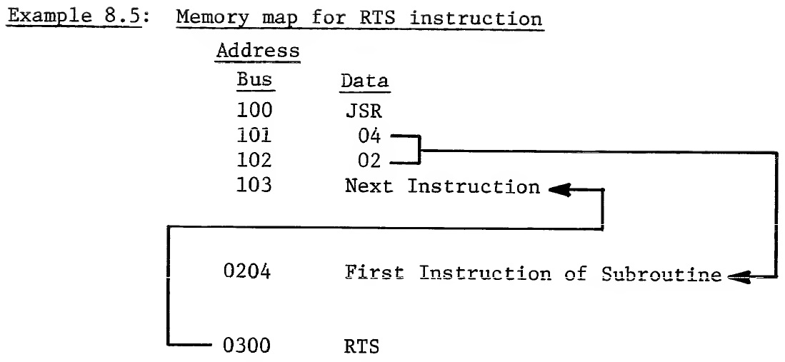
With this capability of subroutining, the microprocessor allows the programmer to go from the main program to 1 subroutine, to the second subroutine, to a third subroutine, then finally working its way back to the main program. Example 8.6 is an expansion of Example 8.2 with the returns included.
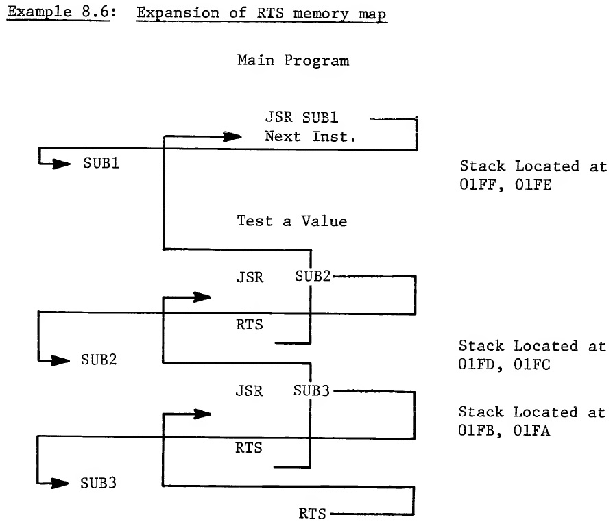
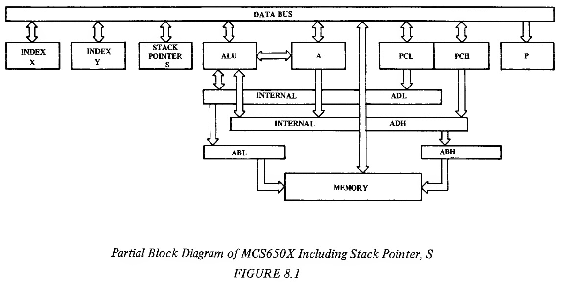
This concept is known as nesting of subroutines, and the number of subroutines which can be called and returned from in such a manner is limited by only the length of the stack. 8.3 IMPLEMENTATION OF STACK IN MCS6501 THROUGH MCS6505 As we have seen, the primary requirement for the stack is that irrespective of where or when a stack operation is called, the microprocessor must have an independent counter or register which contains the current memory location value of the stack address. This register is called the Stack Pointer, S. The stack becomes an auxiliary field in memory which is basically independent of programmer control. We will discuss later how the stack pointer becomes initialized, but once it is initialized, the primary requirement is that it be self-adjusted; in other words, operations which put data on the stack cause the pointer to be decremented automatically; operations which take data off from the stack cause the pointer to be incremented automatically. Only under rare circumstances should the programmer find it necessary to move his stack from one location to another if he is using the stack as designed. On this basis, there is no need for a stack to be longer than 256 bytes To perform a single subroutine call takes only 2 bytes of stack memory. To perform an interrupt takes only 3 bytes of stack memory. Therefore, with 256 bytes, one can access 128 subroutines deep or interrupt ourselves 85 times. Therefore the length of the stack is extremely unlikely to be limiting. The MCS6501 through MCS6505 have a 256-byte stack length. Figure 8.1, which is now the complete block diagram, shows all of the microprocessor registers. The 8-bit stack pointer register, S, has been added. It is initialized by the programmer and thereafter automatically increments or decrements , depending on whether data is being put on to the stack or taken off the stack by the microprocessor under control of the program or the interrupt lines.
The primary purpose of the stack is to furnish a block of memory locations in which the microprocessor can write data such as the program counter for use in later processing. In many control systems the requirements for Read/Write memory are very small and the stack just represents another demand on Read/Write memory. Therefore these applications would like the stack to be in the Page Zero location in order that memory allocation for the stack, the Zero Page operations, and the indirect addresses can be performed. Therefore, one of the requirements of a stack is that it be easily locatable into Page Zero. On the other hand, if more than 1 page of RAM is needed because of the amount of data that must be handled by the user programs, having the stack in Page Zero is an unnecessary waste of Page Zero memory in the sense that the stack can take no real advantage of being located in Zero Page, whereas other operations can. In each of the examples, the stack has been located at high order address 01 followed by a low order address . In the same manner as the microprocessor forces locations 00 on to the high order 8 bits of the address lines for Zero Page operations, the microprocessor automatically puts 01 Hex on to the high order 8-bit address lines during each stack operation. This has the advantage to the user of locating the stack into Page One of memory which would be the next memory location added if the Zero Page operation requirements exceed Page Zero memory capacity. This has the advantage of the stack not requiring memory to be added specifically for the stack but only requiring the allocation of existing memory locations. It should be noted that the selected addressing concepts of the MCS650X microprocessor support devices would involve connecting the memories such that bit 8, which is the selection bit for the Page One versus Page Zero, is a "don't care" for operations in which the user does not need more than 1 page of Read/Write memory. This gives the user the effect of locating stack in Page Zero for those applications. The second feature that should be noted from the examples is that the stack was located at the end of Page One and decremented from that point towards the beginning of the page. This is the natural operation of the stack. RAM memory comes in discrete increments, 64, 128, 256 bytes so the normal method of allocating stack addressing is for the user to calculate the number of bytes probably needed for stack access. This could be done by analyzing the number of subroutines which might be called and the amount of data which might be put onto the stack in order to communicate between subroutines or the number of interrupts plus subroutines which might occur with the respective data that would be stored on the stack for each of them. By counting 3 bytes for each interrupt, 2 bytes for each jump to subroutine, plus 1 byte for each programmer-controlled stack operation, the microprocessor designer can estimate the amount of memory which must be allocated for the stack. This is part of his decision-making process in deciding how much memory is necessary for his whole program. Once the allocation has been made, it is recommended that the user assign his working storage from the beginning of memory forward and always load his stack at the end of either Page Zero, Page One, or at the end of his physical memory which is located in one of those locations. This will give the effect of having the highest bytes of memory allocated to the stack, lower bytes of memory allocated to user working storage and hopefully the two shall never overlap. It should be noted that the natural operation of the stack, which often is called by hardware not totally under program control, is such that it will continue to decrement throughout the page to which it is allocated irrespective of the user's desire to have it do so. A normal mistake in allocation in memory can result in the user writing data into a memory location and later accessing it with another subroutine or another part of his program, only to find that the stack has very carefully written over that area as the result of its performing hardware control operations . This is one of the more difficult problems to diagnose. If this problem is suspected by the programmer, he should analyze memory locations higher than unexplained disturbed locations. There is a distinctive pattern for stack operations which are unique to the user's program but which are quite predictable. An analysis of the value which has been destroyed will often indicate that it is part of an which would normally be expected during the execution of the program between the time data was stored and the time it was fetched. This is a very strong indication of the fact that the stack somehow or other did get into the user's program area. This is almost always caused by improper control of interrupt lines or unexpected operations of interrupt or subroutine calls and has only 2 solutions: (1) If the operation is normal and predictable, the user must assign more memory to his program and particularly reassign his memory such that the stack has more room to operate; or (2) if the operation of the interrupt lines is not predictable, attention must be given to solving the hardware problem that causes this type of unpredictable operation. 8.3.1 Summary of Stack Implementation The MCS6501 through MCS6505 microprocessors have a single 8-bit stack register. This register is automatically incremented and decremented under control of the microprocessor to perform stack manipulation operations, under direction of the user program or the interrupt lines. Once the programmer has initialized the stack pointer to the end of whatever memory he wants the stack to operate in, the programmer can ignore stack addressing other than in those cases where there is an interference between stack operations and his normal program working space. In the MCS6501 through MCS6505, the stack is automatically located in Page One. The microprocessor always puts out the address 0100 plus stack register for every stack operation. By selected memory techniques, the user can either locate the stack in Page Zero or Page One, depending on whether or not Page One exists for his hardware. 8.4 USE OF THE STACK BY THE PROGRAMMER Discussed in Section 8.1 was the use of the JSR to call a subroutine. However, not indicated was the technique by which the subroutine knew which data to operate on. There are 3 classical techniques for communicating data between subroutines. The first and most straightforward technique is that each subroutine has a defined set of working registers located in the Page Zero in which the user has left values to be operated on by the subroutine. The registers can either contain the values directly or can contain indirect pointers to addresses to values which would be operated on. The following example shows the combination of these: Example 8.7: Call-a-move subroutine using preassigned memory locations Location 10 = Count Location 11, 12 = Base from Address Location 13, 14 = Base to Address Main Line Routine No. of Bytes Instruction Comment 2 LDA #Count -1 Load Fixed Value for the Move 2 STA 10 2 LDA #FRADH 2 STA 12 Set up "FROM" Pointer 2 LDA #FRADL 2 STA 11 2 LDA #TOADL 2 STA 13 2 LDA #TOADH 2 STA 14 Set up "TO" Pointer 3 JSR SUB1 23 bytes Subroutine Coding No. of Bytes Label Instruction 2 SUB1 LDY 10 2 LOOP LDA (11), Y 2 STA (13), Y 1 DEY 2 BNE LOOP 1 RTS total 33 bytes As has been previously developed, the loop time is the overriding consideration rather than setup time for a large number of executions. It can be seen that we have used the techniques developed in previous sections of the indirect referencing, the jump to subroutine and the return from subroutine to perform this type of subroutine value communication. In this operation, there was no use of the stack except for the program counter value. A second form of communication is the use of the stack itself as an intermediate storage for data which is going to be communicated to the subroutine. In order for the programmer to use the stack as an intermediate storage, he needs instructions which allow him to put data on the stack and to read from the stack. These instructions are known as push and pull instructions. 8.5 PHA - PUSH ACCUMULATOR ON STACK This instruction transfers the current value of the accumulator to the next location on the stack, automatically decrementing the stack to point to the next empty location. The symbolic notation for this operation is A^. Noted should be that the notation 4- means push to the stack, f means pull from the stack. The Push A instruction only affects the stack pointer register which is decremented by 1 as a result of the operation. It affects no flags. PHA is a single-byte instruction and its addressing mode is Implied. The following example shows the operations which occur during Push A instruction. Example 8.8: Operation of PHA, assuming stack at 01FF External Internal Cycle Address Bus Data Bus Operations Operations 1 0100 OP CODE Fetch Finish Previous Instruction Operation, Increment PC to 0101 2 0101 Next Fetch Next Interpret PHA Instruction, OP CODE OP CODE Hold and Discard P-Counter 3 01FF (A) Write A on Decrement Stack Stack Pointer to 01FE 4 0101 Next Fetch Next OP CODE OP CODE As can be seen, the PHA takes 3 cycles and takes advantage of the fact that the stack pointer is pointing to the correct location to write the value of A. As a result of this operation, the stack pointer will be setting at 01FF. The notation (A) implies contents of A. Now that the data is on the stack, later on in the program the programmer will call for the data to be retrieved from the stack with a PLA instruction. 8.6 PLA - PULL ACCUMULATOR FROM STACK This instruction adds 1 to the current value of the stack pointer and uses it to address the stack and loads the contents of the stack into the A register. The symbolic notation for this is A↑. The PLA instruction does not affect the carry or overflow flags. It sets N if the bit 7 is on in accumulator A as a result of instructions, otherwise it is reset. If accumulator A is zero as a result of the PLA, then the Z flag is set, otherwise it is reset. The PLA instruction changes content of the accumulator A to the contents of the memory location at stack register plus 1 and also increments the stack register. The PLA instruction is a single-byte instruction and the addressing mode is Implied. In the following example, the data stored on the stack in Example 8.8 is transferred to the accumulator. Example 8.9: Operation of PLA stack from Example 8.8 External Internal Cycle Address Bus Data Bus Operations Operations 1 0200 PLA Fetch Finish Previous Operation, Instruction Increment PC to 101 2 0201 Next Fetch Next Interpret Instruction, OP CODE OP CODE and Hold P-Counter Discard 3 01FE Read Stack Increment Stack Pointer to 01FF 4 01FF (A) Fetch A Save Stack 5 0201 Next Fetch Next M → A OP CODE OP CODE When taking data off the stack, there is 1 extra cycle during which time the current contents of the stack register are accessed but not used and the stack pointer is incremented by 1 to allow access to the value that was previously stored on the stack. The stack pointer is left pointing at this location because it is now considered to be an empty location to be used by the stack during a subsequent operation. 8.7 USE OF PUSHES AND PULLS TO COMMUNICATE VARIBLES BETWEEN SUBROUTINE OPERATIONS In Example 8.10, we perform the same operation as we did in Example 8.7; only here, instead of using fixed locations to pick up the pointers, we are going to use the stack as a communications vehicle: Example 8.10: Call-a-move subroutine using the stack to communicate Location 11, 12 = Base "FROM" Address Location 13, 14 = Base "TO" Address Main Line Routine Bytes Instruction 2 LDA #Count -1 1 PHA 2 LDA #FRADL 1 PHA 2 LDA #FRADH 1 PHA 2 LDA #TOADL 1 PHA 2 LDA #TOADH 1 STA 14 Set up "TO" Pointer 3 JSR SUB1 18 Subroutine Bytes Label Instruction Comments 2 SUB1 LDX 6 1 LOOP1 PLA 2 STA 10,X 1 DEX Move Stack to Memory 2 BNE LOOP 1 2 PLA Set up Count 2 TAY 2 LOOP2 LDA (11),Y 2 LDA (13),Y Move Memory Location 2 DEY 2 BNE LOOP 2 2 LDA 15 2 PHA 2 LDA 16 Restore PC to Stack 2 PHA 1 RTS Total 42 Bytes We can see from this example that using the stack as a communication vehicle actually increases the number of bytes in the subroutine and the total bytes overall. However, the only time one should be using subroutines in this case is when the subroutine is fairly long and the number of times the subroutine is used is fairly frequent. This technique does reduce the number of bytes in the calling sequence. The calling sequence is normally repeated once for every time the instruction is called; therefore the use of the stack to communicate should result in a net reduction in the number of bytes used in the total program. Up until this time, we have been considering that the stack is at a fixed location and that all stack references use the stack pointer. It has not been explained how the stack pointer in the microprocessor gets loaded and accessed. This is done through communication between the stack pointer and index register X. 8.8 TXS - TRANSFER INDEX X TO STACK POINTER This instruction transfers the value in the index register X to the stack pointer. Symbolic notation is X → S. TXS changes only the stack pointer, making it equal to the content of the index register X. It does not affect any of the flags. TXS is a single-byte instruction and its addressing mode is Implied Another application for TXS is the concept of passing parameters to the subroutine by storing them immediately after the jump to subroutine instruction. In Example 8.11, the from and to address, plus the count of number of values would be written right after the JSR instruction and its address. By locating the stack in Page Zero, the address of the last byte of the JSR can be incremented to point at the parameter bytes and then used as an indirect pointer to move the parameter to its memory location. The key to this approach is transferring the stack pointer to X which allows the program to operate directly on the address while it is in the stack. It should be noted that this approach automatically leaves the address on the stack, positioned so that the RTS picks up the next OP CODE address. Example 8.11: Jump to subroutine (JSR) followed by parameters Address Bus Data 0100 JSR 0101 ADL 0102 ADH 0103 To High 0104 To Low 0105 From High 0106 From Low 0107 Count 0108 Next OP CODE Before concluding this discussion on subroutines and parameter passing, one should again note the use of subroutines should be limited to those cases where the user expects to duplicate code of significant length several times in the program. In these cases, and only in these cases, is subroutine call warranted rather than the normal mode of knowing the addresses and specifying them in an instruction. In all cases where timing is of significant interest, subroutines should also be avoided. Subroutines add significantly to the setup and execution time of problem solution. However, subroutines definitely have their place in microcomputer code and there have been presented 3 alternatives for use in application programs. The user will find a combination of the above techniques most useful for solving his particular problem. 8.9 TSX - TRANSFER STACK POINTER TO INDEX X This instruction transfers the value in the stack pointer to the index register X. Symbolic notation is S → X. TSX does not affect the carry or overflow flags. It sets N if bit 7 is on in index X as a result of the instruction, otherwise it is reset. If index X is zero as a result of the TSX, the Z flag is set, otherwise it is reset. TSX changes the value of index X, making it equal to the content of the stack pointer. TSX is a single-byte instruction and the addressing mode is Implied. 8.10 SAVING OF THE PROCESSOR STATUS REGISTER During the interrupt sequences, the current contents of the processor status register (P) are saved on the stack automatically. However, there are times in a program where the current contents of the P register must be saved for performing some type of other operation. A particular example of this would be the case of a subroutine which is called independently and which involves decimal arithmetic. It is important that the programmer keeps track of the arithmetic mode the program is in at all times. One way to do this is to establish the convention that the machine will always be in binary or decimal mode, with every subroutine changing its mode being responsible for restoring it back to the known state. This is a superior convention to the one that is about to be described. A more general convention would be one in which the subroutine that wanted to change modes of operation would push P onto the stack, then set the decimal mode to perform the subroutine and then pull P back from the stack prior to returning from the subroutine. Instructions which allow the user to accomplish this are as follows: 8.11 PHP - PUSH PROCESSOR STATUS ON STACK This instruction transfers the contents of the processor status register unchanged to the stack, as governed by the stack pointer. Symbolic notation for this is P↓. The PHP instruction affects no registers or flags in the microprocessor. PHP is a single-byte instruction and the addressing mode is Implied 8.12 PLP - PULL PROCESSOR STATUS FROM STACK This instruction transfers the next value on the stack to the Processor Status register, thereby changing all of the flags and setting the mode switches to the values from the stack. Symbolic notation is P↑. The PLP instruction affects no registers in the processor other than the status register. This instruction could affect all flags in the status register. PLP is a single-byte instruction and the addressing mode is Implied. 8.13 SUMMARY ON THE STACK The stack in the MCS650X family is a push-down stack implemented by a processor register called the stack pointer which the programmer initializes by means of a Load X immediately followed by a TXS instruction and thereafter is controlled by the microprocessor which loads data into memory based on an address constructed by adding the contents of the stack pointer to a fixed address. Hex address 0100. Every time the microprocessor loads data into memory using the stack pointer, it automatically decrements the stack pointer, thereby leaving the stack pointer pointing at the next open memory byte. Every time the microprocessor accesses data from the stack, it adds 1 to the current value of the stack pointer and reads the memory location by putting out the address 0100 plus the stack pointer. The status register is automatically pointing at the next memory location to which data can now be written. The stack makes an interesting place to store interim data without the programmer having to worry about the actual memory location in which data will be directly stored. There are 8 instructions which affect the stack. They are: BRK, JSR, PHA, PHP, PLA, PLP, RTI, and RTS. BRK and RTI involve the handling of the interrupts.