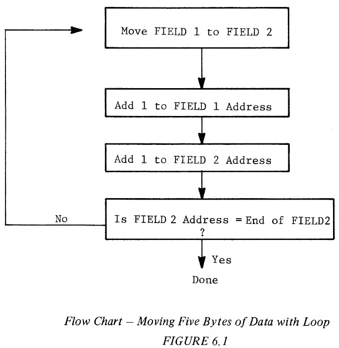
Example 6.2 is a program listing that corresponds to the flow chart: Example 6.2: Moving Five Bytes of Data With Loop LABEL INSTRUCTION OPERAND COMMENTS INITIALIZE CLC START LDA FIELD 1 ─────────┐ OTHER STA FIELD 2 ─────────┘ Move Loop LDA START + 1 ───────┐ ADC #1 │ STA START + 1 │ LDA OTHER + 1 │ Modify Move Values ADC #1 │ STA OTHER + 1 ───────┘ CMP #FIELD 2 + 5 ──── Check for End BNE START NOTE: For ease of reading, labels have been written in the form "FIELD 1", This is incorrect format for use in the various symbolic assemblers. "FIELD 1" must be written "FIELDl" when coding for assembler formats. Assuming Zero Page, direct addressing, Example 6.3 is written below with one byte per line just as it would appear in program memory. This will provide a more detailed description of Example 6.2. Example 6.3: Coded Detail of Moving Fields With Loop LABEL CODE NAMES COMMENTS CLC Clear Carry START LDA (FIELD 1) → A FIELD 1 OTHER STA A → (FIELD 2) FIELD 2 LDA From Address → A START + 1 ADC A + 1 → A 1 STA A → From Address START + 1 LDA To Address → A OTHER + 1 ADC A + 1 → A 1 STA A + To Address OTHER + 1 CMP A - ORIGINAL FIELD 2 + 5 ORIGINAL FIELD 2 + 5 BNE If not, loop to START START In this example, the program is modifying the addresses of one load instruction and one store instruction rather than writing ten instructions to move five bytes of data and fifty instructions to move twenty-five bytes of data. The address of the Load A instruction is located in memory at START + 1 and the Store instruction at OTHER + 1. In order to perform this operation, the address must be modified once for each move operation until all of the data is moved. Checking for the end of the moves is accomplished by checking the results of the address modification to determine if the address exceeds the end of the second field. When it does, the routine is complete. If a hundred values were to be moved this program would remain 20 bytes long, whereas the solution to the first problem would require a program of 200 instructions. The type of coding used in this example is called a "loop". Although the program loop in this case requires as many bytes as the original program, more values could be moved without increasing the length of the program. The greater the number of repetitive operations that are to be accomplished, the greater the advantage of the loop type program over straight line programming. Important Note: The execution time required to move the five values is significantly longer using the loop program than the straight line program. In the straight line program, if a Zero Page operation is assumed, the time to perform the total move is 30 cycles. Using the loop program, the execution time to move five values is five times through the entire loop, which takes 25 cycles. Therefore the time to move five values is 125 cycles. While loops have an advantage in coding space efficiency, all loops cost time. If the programmer has a problem that is extremely time dependent, taking the loop out and going to straight line programming, even though it is extremely inefficient in terms of its utilization of memory, will often solve the timing problem. The straight line programming technique becomes very useful in some control applications. However, it is not recommended as a standard technique but should only be used when there are extreme timing problems, Using loops will normally save a significant number of bytes but they will always take more time. The technique used in the loop program example has two major problems: 1. The necessity to modify program memory. This should be avoided to take advantage of the ability to put programs into read only memory with the corresponding savings in hardware costs. 2. Although this is the simplist form of computed addressing, less program bytes would be necessary than the more sophisticated form of program shown in the following flow chart:
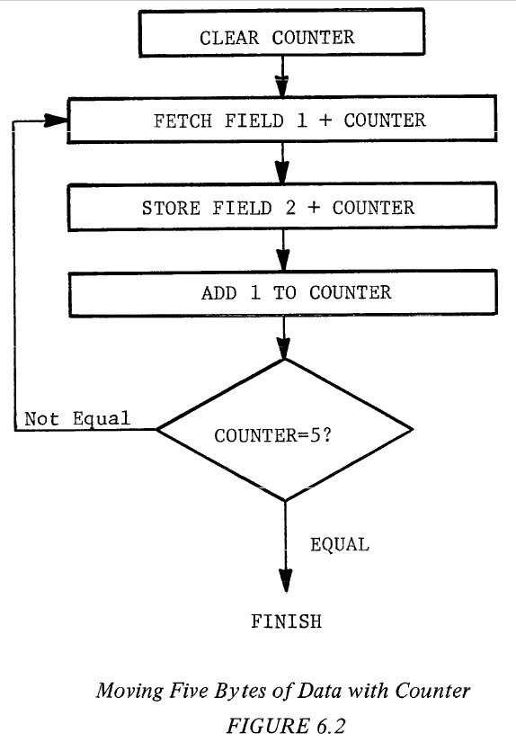
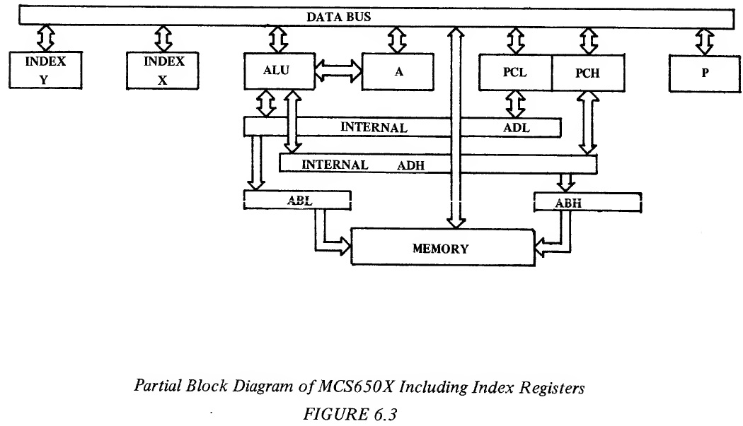
In the MCS650X microprocessor family, the counter is called an index register. It is an 8-bit register which is loaded from memory and has the ability to have one added to it by an increment instruction (INX,INY) and can be compared directly to memory using the compare index instruction (CPX,CPY). Example 6.4 shows the program listing for the flow chart of Figure 6.2. Example 6.4: Moving Five Bytes of Data With Index Registers BYTES LABEL INSTRUCTION OPERAND COMMENTS 2 LDX 0 Load Index With Zero 3 LOOP LDA FIELD 1,X 3 STA FIELD 2,X 1 INX Increment Count 2 CPX 5 Compare For End 2 BNE LOOP 13 for Absolute In this example, index register X is used as an index and as a counter. It is initialized to zero. Data is fetched from memory at the address "FIELD 1 plus the value of register X", and placed in A. The data is then written from A to memory at the address "FIELD 2 plus the value of register X". Register X is incremented by one and compared with 5 in order to determine if all five data values have been transferred. If not the program loops back to LOOP. In this example. "FIELD 1" is called the "Base Address" which is the address to which indexing is referenced. This only takes 11 or 13 bytes, depending on whether or not the field is in Page Zero or in absolute memory. It still takes 13 or 15 cycles per byte moved, again confirming that loops are excellent for coding space but not for execution time. It can be seen from the example that there are basically two criterias for an index register; one, that it be a register which is easily incremented, compared, loaded, and stored, and two, that in a single instruction one can specify both the Base Address and the value of X. In the MCS650X microprocessor, the way that the indexed instruction is symbolically represented is OP CODE, Address, X. This indicates to the symbolic assembler that an instruction OP CODE should be picked, which should specify either the absolute address modified by the content of index X register. In performing these operations, the microprocessor fetches the instruction OP CODE as previously defined, and fetches the address, modifies the address from the memory by adding the index register to it prior to loading or storing the value of memory. The index register is a counter. As discussed previously, one of the advantages of the flags in the microprocessor is that a value can be modified and its results tested. Assume the last example is modified so that instead of moving the first value in FIELD 1 to the first value in FIELD 2, the last value in FIELD 1 is moved first to the last value in FIELD 2, then the next to the last value, etc. and finally the first value. With the index register preloaded with 5 and using a decrement instruction the contents of the index register would end at zero after the 5 fields of data were transferred. The zero indicates that the number of times through the loop is correct and the loop exited by use of the zero test. The program listing for this modification is shown in Example 6.5: Example 6.5: Moving Five Bytes of Data By Decrementing the Index Register LABEL INSTRUCTION OPERAND LDX 5 LOOP LDA FIELD 1-1,X STA FIELD 2-1,X DEX BNE LOOP In this example, Index Register X is again used as an Address Counter but it will count backwards. It is initialized to five for this example. Data is fetched from memory at the address "FIELD 1 plus the value of Register X" and placed in A. The data is then written from A to memory at the address "FIELD 2 plus the value of Register X." Register X is decremented by one. If the decremented value is not zero, as determined by a Branch on Zero instruction, the program loops back to LOOP. The loop has been decreased to 9 or 11 bytes and the execution time per byte has been decreased from 15 cycles to 13 cycles per value which shows the advantage of using the flag setting of the decrement index instruction. The two index registers, X and Y, can now be added to the system block diagram as in Figure 6.3
Each of the index registers is 8 bits long and is loaded and stored from memory, using techniques similar to the accumulator. Because of this ability, they can be considered as auxiliary channels to flow data through the microprocessor. However, their primary use is in being added to addresses fetched from memory to form a modified effective address, as described previously. Both index registers have the ability to be compared to memory (CPX,CPY) and to be incremented (INX,INY) and decremented (DEX,DEY). Because of OP CODE limitations, X and Y have slightly different uses. X is a little more flexible because it has Zero Page operations which Y does not have with exception of LDX and STX. Aside from which modes they modify j the registers are autonomous j independent and of equal value. 6.1 ABSOLUTE INDEXED Absolute indexed address is absolute addressing with an index register added to the absolute address. The sequences that occur for indexed absolute addressing without page crossing are as follows: Example 6.6: Absolute Indexed; With No Page Crossing Address Data External Internal Cycle Bus Bus Operation Operation 1 0100 OP CODE Fetch OP CODE Increment PC to 101, Finish Previous Instruction 2 0101 BAL Fetch BAL Increment PC to 102, Interpret In- struction 3 0102 BAH Fetch BAH Increment PC to 103, Calculate BAL + X 4 BAH,BAL+X OPERAND Put Out Effective Address 5 103 Next OP Fetch Next Finish Operations CODE OP CODE BAL and BAH refer to the low and high order bytes of the base address, respectively. While the index X was used in Example 6.7, the index Y is equally applicable. If a page is not crossed, the results of the address low + X does not cause a carry. The processor is able to pipeline the addition of the 8-bit index register to the lower byte of the base address (BAL) and not suffer any time degradation for absolute indexed addressing over straight absolute addressing. In other words, while BAH is being fetched, the add of X to BAL occurs. Both addressing modes require four cycles with the only difference being that X or Y must be set at a known value and the OP CODE must indicate an index X or Y. The second possibility is that when the index register is added to the address low of the base address that the resultant address is in the next page. This is illustrated in Example 6.7. Example 6.7: Absolute Indexed; With Page Crossing Address Data External Internal Cycle Bus Bus Operation Operation 1 0100 OP CODE Fetch OP CODE Finish Previous Operation Increment PC to 101 2 0101 BAL Fetch BAL Interpret Instruction Increment PC to 102 3 0102 BAH Fetch BAH Add BAL + Index Increment PC to 103 4 BAH,BAL Data Fetch Data Add BAH + Carry +X (Ignore) (Data is ignored) 5 BAH+1, Data Fetch Data BAL+X 6 103 Next OP Fetch Next Finish Operation CODE OP CODE The most substantial difference between the page crossing operation and no page crossing is that during the fourth cycle, the address high and the calculated address low is put out, thereby incorrectly addressing the same page as the base address. This operation is carried on in parallel with the adding of the carry to the address high. During the fourth cycle the address high plus the carry from the adder is put on the address bus, moving the operation to the next page. Thus there are two effects from the page crossing. 1. The addressing of a false address. This is similar to what happens in a branch relative during a page crossing. 2. The operation takes one additional cycle while the new address high is calculated. As with the branch relative this page crossing occurs independently of programmer action and there is no penalty in memory for having crossed the page boundary. It is possible for the programmer to predict a page crossing by knowing the value of the base address and the maximum offset value in the index register. If timing is of concern, the base address can be adjusted so that the address field is always in one page. As with absolute addressing, absolute indexed is the most general form of indexing. It is possible to do absolute indexed modified by X, and absolute indexed modified by Y. Instructions which allow absolute indexed by X are ADC, AND, ASL, CMP, DEC, EOR, INC. LDA, LDY, LSR, ORA, ROL, SBC, and STA. The instructions which allow indexed absolute by Y are ADC, AND, CMP, EOR, LDA, LDX, ORA, SBC, and STA. 6.2 ZERO PAGE INDEXED As with non-computed addressing, there is a memory use advantage to the short-cut of Zero Page addressing. Except in LDX and STX instructions which can be modified by Y, Zero Page is only available modified by X. If the base address plus X exceeds the value that can be stored in a single byte, no carry is generated, therefore there is no page crossing phenomena. A wrap-around will occur within Page Zero. The following example illustrates the internal operations of Zero Page indexing. Example 6.8: Illustration of Zero Page Indexing Address Data External Internal Cycle Bus Bus Operation Operation 1 0100 OP CODE Fetch OP CODE Finish Previous Operation, 0101 → PC 2 0101 BAL Fetch Base Interpret Instruct- Address Low ion, 0102 → PC (BAL) 3 00,BAL Data Fetch Add: BAL + X (Dis- Discarded carded Data 4 00,BAL Data Fetch Data +X 5 0102 Next OP Fetch Next OP Finish Operation CODE CODE As can be seen from the example, there is no time savings of Zero Page indexing over absolute indexing without page crossing. In the case of the indexed absolute during cycle 3 the address high is being fetched at the same time as the addition of the index to address low. In the case of the Zero Page, there is no opportunity for this type of overlap; therefore, indexed Zero Page instructions take one cycle longer than non-indexed instructions. In both Zero Page indexed and absolute indexed with a page crossing, there are incorrect addresses calculated. Provisions have been made to make certain that only a READ operation occurs during this time. Memory modifying operations such as STORE, SHIFT, ROTATE, etc. have all been delayed until the correct address is available, thereby prohibiting any possibility of writing data in an incorrect location and destroying the previous data in that location. As has been previously stated, there is no carry out of the Zero Page operation. 00 is forced into address high under all circumstances in cycle 4. For example, if the index register containing a value of 10 is to be added to base address containing a value of F7, the following operation would occur: Example 6.9: Demonstrating the Wrap-Around Cycle Address Bus Internal Operation 3 00F7 F7 + 10 4 0007 This indicated the wrap-around effect that occurs with Zero Page indexing with page crossing. This wrap-around does not increase the cycle time over that shown in the previous example. Only index X is allowed as a modifier in Zero Page. Instructions which have this feature include ADC, AND, ASL, CMP, DEC, EOR, INC, LDA, LDY, LSR, OKA, ROL, SBC, STA and STY. Note that index Y is allowed in the instructions LDX and STX. 6.3 INDIRECT ADDRESSING In solving a certain class of problems, it is sometimes necessary to have an address which is a truly computed value, not just a base address with some type of offset, but a value which is calculated or sometimes obtained as a group of addresses. In order to implement this type of indexing or addressing, the use of indirect addressing has been introduced. In the MCS650X family indirect operations have a special form. The basic form of the indirect addressing is that of an instruction consisting of an OP CODE followed by a Zero Page address. The microprocessor obtains the effective address by picking up from the Zero Page address the effective address of the operation. The indirect addressing operation is much the same as absolute addressing except indirect addressing uses a Zero Page addressing operation to indirectly access the effective address. In "the case of absolute addressing the value in the program counter is used as the address to pick up the effective address low, one is added to the program counter which is used to pick up the effective address high. In the case of indirect addressing, the next value after the OP CODE, as addressed with the program counter, is used as a pointer to address the effective address low in the zero page. The pointer is then incremented by one with the effective address high fetched from the next memory location. The next cycle places the effective address high (ADH) and effective address low (ADL) on the address bus to fetch the data. An illustration of this is shown in Figure 6.4.
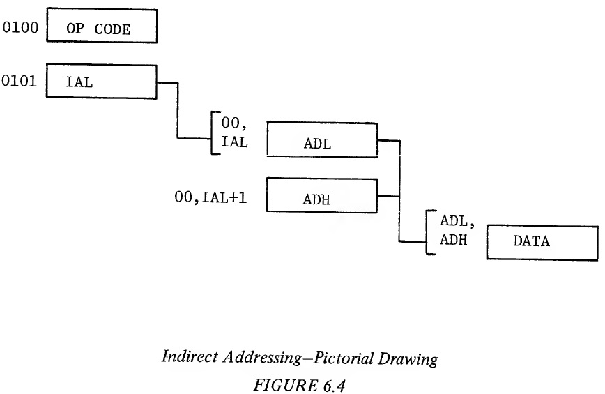
The address following the instruction is really the address of an address, or "indirect" address. The indirect address is represented by IAL in the figure. A more detailed definition of indirect addressing is included in the appendix. Although the MCS650X microprocessor family has indirect operations, it has no simple indirect addressing such as described above. There are two modes of indirect addressing in the MCS650X microprocessor family? 1.) indexed indirect and 2.) indirect indexed. 6.4 INDEXED INDIRECT ADDRESSING The major use of indexed indirect is in picking up data from a table or list of addresses to perform an operation. Examples where indexed indirect is applicable is in polling I/O devices or performing string or multiple string operations. Indexed indirect addressing uses the index register X. Instead of performing the indirect as shown in the Figure 6.4, the index register X is added to the Zero Page address, thereby allowing varying address for the indirect pointer. The operation and timing of the indexed indirect addressing is shown in Figure 6.5.
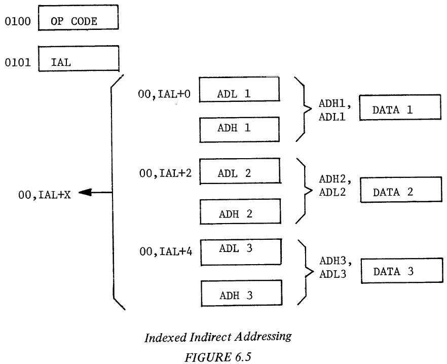
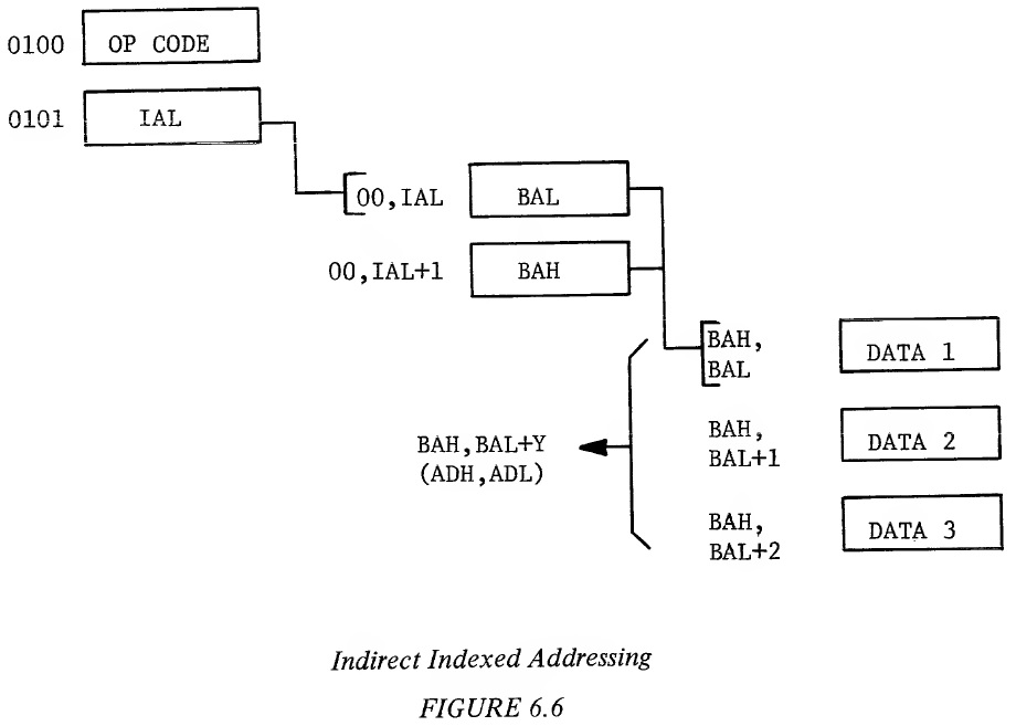
Example 6.10: Illustration of Indexed Indirect Addressing Address Data External Internal Cycle Bus Bus Operation Operation 1 0100 OP CODE Fetch OP CODE Finish Previous Operation, 0101 → PC 2 0101 BAL Fetch BAL Interpret In- struction, 0102 → PC 3 00,BAL DATA (Dis- Fetch Discard- Add BAL + X carded) ed Data 4 00,BAL ADL Fetch ADL Add 1 to BAL + X + X 5 00,BAL ADH Fetch ADH Hold ADL + X + 1 6 ADH,ADL DATA Fetch DATA 7 0102 Next OP Fetch Next OP Finish Operation CODE 0103 → PC One of the advantages of this type of indexing is that a 16-bit address can be fetched with only two bytes of memory, the byte that contains the OP CODE and the byte that contains the indirect pointer. It does require, however, that there be a table of addresses kept in a read/write memory which is more expensive than having it in read only memory. Therefore, this approach is normally reserved for applications where use of indexed indirect results in significant coding or throughput improvement or where the address being fetched is a variable computed address. It is also obvious from the example that the user pays a minor time penalty for this form of addressing in that indexed indirect always takes six cycles to fetch a single operand which is 25% more than an absolute address and 50% more than a Zero Page reference to an operand. As in the Zero Page indexed, the operation in cycles three and four are located in Zero Page and there is no ability to carry over into the next page. It is possible to develop a value of the index plus the base address where the result exceeded 255, in this case the address put out is a wrap-around to the low part of the Page Zero. Instructions which allow the use of indexed indirect are ADC, AND, CMP, EOR, LDA, ORA, SBC, STA. 6.5 INDIRECT INDEXED ADDRESSING The indirect indexed instruction combines a feature of indirect addressing and a capability of indexing. The usefulness of this instruction is primarily for those operations in which one of several values could be used as part of a subroutine. By having an indirect pointer to the base operation and by using the index register Y in the normal counter type form, one can have the advantages of an address that points anywhere in memory, combined with the advantages of the counter offset capability of the index register. Figure 6.6 illustrates the indirect indexed concept in flow form while Example 6.11 indicates the internal operation of a non-page rollover of an indirect index.
Example 6.11: Indirect Indexed Addressing (No Page Crossing) Address Data External Internal Cycle Bus Bus Operation Operation 1 0100 OP CODE Fetch OP CODE Finish Previous Operation, 0101 → PC 2 0101 IAL Fetch IAL Interpret In- struction, 0102 → PC 3 00,IAL BAL Fetch BAL Add 1 to IAL 4 00,IAL BAH Fetch BAH Add BAL + Y + 1 5 BAH,BAL DATA Fetch Operand + Y 6 0102 Next OP Fetch Next OP Finish Operation CODE CODE 0103 → PC The indirect index still requires two bytes of program storage, one for the OP CODE, one for the indirect pointer. Once beyond the indirect, the indexing of the indirect memory location is just the same as though it was an absolute indexed operation in the sense that if there is no page crossing, pipelining occurs in the adding of the index register Y to address low while fetching address high, and therefore, the non-page crossing solution is one cycle shorter than the indexed indirect. In Example 6.12 it is seen that the page crossing problem that occurs with absolute indexed page crossing also occurs with indirect indexed addressing. Example 6.12: Indirect Indexed Addressing (With Page Crossing) Address Data External Internal Cycle Bus Bus Operation Operation 1 0100 OP CODE Load OP CODE Finish Previous Operation, 0101 → PC 2 0101 IAL Fetch IAL Interpret In- struction, 0102 → PC 3 00,IAL BAL Fetch BAL Add 1 to IAL 4 00,IAL BAH Fetch BAH Add BAL to Y + 1 5 BAH,BAL DATA (Dis- Fetch Data Add 1 to BAH + Y carded) (Discarded) 6 BAH + 1 DATA Fetch Data BAL + Y 7 0102 Next OP Fetch Next OP Finish This CODE CODE Operation, 0103 → PC When there is a page crossing, the base address high and base address low plus Y are pointing to an incorrect location within a referenced page. However, it should be noted that the programmer has control of this incorrect reference in the sense that it is always pointing to the page of the base address. In one more cycle the correct address is referenced. As was true in the case of absolute indexed, the data at the incorrect address is only read. STA and the various read, modify, write memory commands all operate assuming that there will be a page crossing, take the extra cycle time to perform the add and carry and only perform a write on the sixth cycle rather than taking advantage of the five cycle short-cut which is available to read operations. This added cycle guarantees that a memory location will never be written into with incorrect data. Instructions which allow the use of indexed indirect are ADC, AND, CMP, EOR, LDA, ORA, SBC, STA. In the following two examples can be seen a comparison between the use of absolute modified by Y and indirect indexed addressing. In these examples the same function is performed. Values from two memory locations are added and the result stored in a third memory location, assuming that there are several values to be added. The first example deals with known field locations. The second example, such as might be traditionally used in subroutines, deals with field locations that vary between routines. A two byte pointer for each routine using the subroutine is stored in Page Zero. The number of values to be added for each routine is also stored. Example 6.13: Absolute Indexed Add - Sample Program #Bytes Cycles Label Instruction Comments 2 2 START LDY #COUNT -1 Set Y = End of FIELD 3 4 LOOP LDA FIELD 1,Y Load Location 1 3 4 ADC FIELD 2,Y Add Location 2 3 4 STA FIELD 3,Y Store in Location 3 1 2 DEY 2 3 BPL LOOP Check for Less Than Zero __ __ _____________________________________________ 14 19 Time for 10 Bytes = 171 Cycles Example 6.14: Indirect Indexed Add - Sample Program #Bytes Cycles Label Instruction Comments 2 2 START LDY #COUNT -1 Set Y = End of FIELD 2 5 LOOP LDA (PNT1),Y Load FIELD 1 Value 2 5 ADC (PNT2),Y Add FIELD 2 Value 2 5 STA (PNT3),Y Store FIELD 3 Value 1 2 DEY 2 3 BPL LOOP __ __ _____________________________________________ 11 22 Time for 10 Bytes = 201 Cycles The "count" term in these examples represents the number of sets of values to be added and stored. Loading the index register with COUNT-1 will allow a fall through the BPL instruction when computation on all set of values has been completed. There is a definite saving in program storage using indirect because it only requires two bytes for each indirect pointer, the OP CODE plus the pointer of the Page Zero location, whereas in the case of the absolute, it takes three bytes, the OP CODE, address low and address high. It is noted that there are six bytes of Page Zero memory used for pointers, two bytes for each pointer. The number of memory locations allocated to the problem are 17 for the indirect and 14 for the problem where the values are known. The execution time is longer in the indirect loop. Even though the increase in time for a single pass through the loop is only three cycles, if many values are to be transferred, it adds up. It is important to note that loops require time for setup but it is only used once. But in the loop itself, additional time is multiplied by the number of times the program goes through the loop; therefore, on problems where execution time is important, the time reduction effort should be placed on the loop. Even though the loop time is longer and the actual memory expended is greater for the indexed indirect add, it has the advantage of not requiring determination of the locations of FIELD 1, FIELD 2, and FIELD 3 at the time the program was written as is necessary with absolute. An attempt to define problems to take advantage of this shorter memory and execution time by defining fields should be investigated first. However, in almost every program, the same operation must be performed several times. In those cases, it is sometimes more useful to define a subroutine and set the values that the subroutine will operate on as fields in memory. Pointers to these fields are placed in the Zero Page of memory and then the indexed indirect operation is used to perform the function. This is the primary use of the indexed indirect operation. 6.6 INDIRECT ABSOLUTE In the case of all of the indirect operations previously described, the indirect reference was always to a Page Zero location from which is picked up the effective address low and effective address high. There is an exception in the MCS650X microprocessor family for the jump instruction in which absolute indirect jumps are allowed. The use of the absolute indirect jump is best explained in the discussion on interrupts where the addressing mode and its capabilities are explained. 6.7 APPLICATION OF INDEXES As has been developed in many of the previous examples, an index register has primary values as a modifier and as a counter. As a modifier to a base address operation, it allows the accessing of contiguous groups of data by simple modification of the index. This is the primary application of indexes and it is for this purpose they were created. By virtue of the fact that all of the MCS650X instructions have the base address in the instruction, or in the case of the indirect, in the pointer, a single index can usually be used to service an entire loop, because each of the many instructions in the loop normally are referring to the same relative value in each of the lists. An example is adding the third byte of a number to its corresponding third byte of another number, then storing the result in the memory location representing the third byte of the result; therefore, the index register only needs to contain three to accomplish all three of these offset functions. Some other microprocessors use internal registers as indirect pointers. The single register requirement is a significant advantage of the type of indexing done in the MCS650X. Even though the MCS650X has two indexes, more often than not, a single index will solve many of the problems because of the fact that the data is normally organized in corresponding fields. The second feature of the MCS650X type of indexing is that, if used properly, the index register also contains the count of the operations to be performed. The examples have tried to show how to take advantage of that feature. There are two approaches to counting; forward counting and reverse counting. In forward counting, the data in memory can be organized such that the index register starts at zero and is added to on each successive operation. The disadvantage of this type of approach is that the compare index instruction, as used in Example 6.13 must be inserted into the loop in order to determine that the correct number of operations is completed. The reverse counting approach has been used in the latter examples. The data must be organized for reverse counting operation. The first value to be operated on is at the end of the FIELD, the next value is one memory location in front of that, etc. The advantage of this type of operation is that it takes advantage of the combined decrement and test capability of the processor. There are two ways to use the test. First there is the case where the actual number of operations to be performed is loaded into the index register such as was done in Example 6.13. In this case, the index contains the correct count but if added to the base directly, would be pointing to one value beyond the FIELD because the base address contains the first byte. Therefore, when using the actual count in the index register, one always references to the base address minus one. This is easily accomplished as shown in the examples. The cross assembler accepts symbolic references in the form of base address minus one, and the microprocessor very carefully performs the operation shown. The advantage of putting the actual count in the register is that the branch if not equal instruction CBNE) can be used because the value of the register goes to zero on the last operation. The second alternative is to load the counter with the count minus one as done in Example 6.14. In this case, the actual value of the base address is used in the offset. However, the branch back to loop now is a branch plus, remembering that the value in the index register will not go to minus (all ones) until we decrement past zero. Values of count minus one through zero will all take the branch. It is only when attempting to reference less than the base address that the loop will be completed. Either approach gives minimum coding and only requires that the user develop a philosophy of always organizing his data with the first value at the end. In many cases, the operations such as MOVE can be performed even if the data is organized the other way. Experienced programmers find that this reverse counting form is actually more convenient to use and always results in minimum loop time and space. Although for most applications, the 8-bit index register allows simple count in offset operations, there are a few operations where the 256 count that is available in the 8-bit register is not enough problem. First, to code the program with two sets of bases, that is duplicating the coding for the loop with two different address highs, each one a page apart. The second, more useful solution, is to go to indirect operations because the indirect pointer can be modified to allow an infinite indexed operation. An example of the move done under 256 and over 256 is shown in the following example: Example: 6.16: Move N Bytes (N<256) ───────────── ─────────────────── Number of Program Instruction OPERAND Cycles Label Mnemonics FIELD Comments 2 LDX #BLOCK Setup 2 Cycles 4 LOOP LDA FROM-1,X 4 STA TO -1,X LOOP Time: 2 DEX 13 cycles 3 BNE LOOP Memory Required: 11 Bytes Example 6.17: Move N Bytes (N>256) Number of Program Instruction operand Cycles Label Mnemonics FIELD Comments 2 MOVE LDA #FROML 3 STA FRPOINT 2 LDA #FROMH Move from address to 3 STA FRPOINT + 1 an indirect pointer 2 LDA #TOL Move A to address 3 STA TOPOINT to an index pointer 2 LDA #TOH 3 STA TOPOINT + 1 2 LDX #BLOCKS Setup # of 256 blocks 2 LDY #0 to move 5 LOOP LDA (FRPOINT),Y Loop time: 16 cycles/ 6 STA (TOPOINT),Y byte. Move 256 bytes 2 DEY 3 BNE LOOP 5 SPECIAL INC FRPOINT + 1 Increase high 5 INC TOPOINT + 1 pointer 2 DEX 2 BMI OUT Check for last move 3 BNE LOOP 2 LDY #COUNT 3 BNE LOOP Setup last move OUT --- --- Memory Required: 40 Bytes